
Expanded bit map display for mounting on a building surface and a method of creating same

a bit map display and building surface technology, applied in the field of large-scale light displays, can solve the problem that light fixtures are not mounted to a uniform support, and achieve the effect of cost-effectiveness

Inactive Publication Date: 2009-02-12
FLEXTRONICS IND
View PDF23 Cites 9 Cited by
  • Summary
  • Abstract
  • Description
  • Claims
  • Application Information

AI Technical Summary

Benefits of technology

"The present invention provides an improved method for mounting a large-scale display on a building surface, called an \"ebodified mountable display\" (EMD). The EMD is made up of a plurality of light fixtures that are individually mounted to the surface, allowing for the creation of a visually uniform image that is not obstructed or interferred with the building's irregularities. The light fixtures can be mounted in almost any location on the surface, and the orientation of each fixture can be adjusted for optimal viewing from a pre-determined vantage point. The EMD is cost-effective and can be used in various building environments. The technical effects of this invention include increased flexibility in mounting the display, improved image quality, and reduced interference with the building surface."

Problems solved by technology

Therefore, the light fixtures are not mounted to a uniform support, such as a screen, that is then mounted to the building surface.
The building surface may include multiple irregularities, such as windows, air vents, pipes, columns, etc. that interfere with the generally uniform substrate, such as brick or concrete, of the building surface.

Method used


Image

  • Expanded bit map display for mounting on a building surface and a method of creating same
  • Expanded bit map display for mounting on a building surface and a method of creating same
  • Expanded bit map display for mounting on a building surface and a method of creating same

Examples


Embodiment Construction

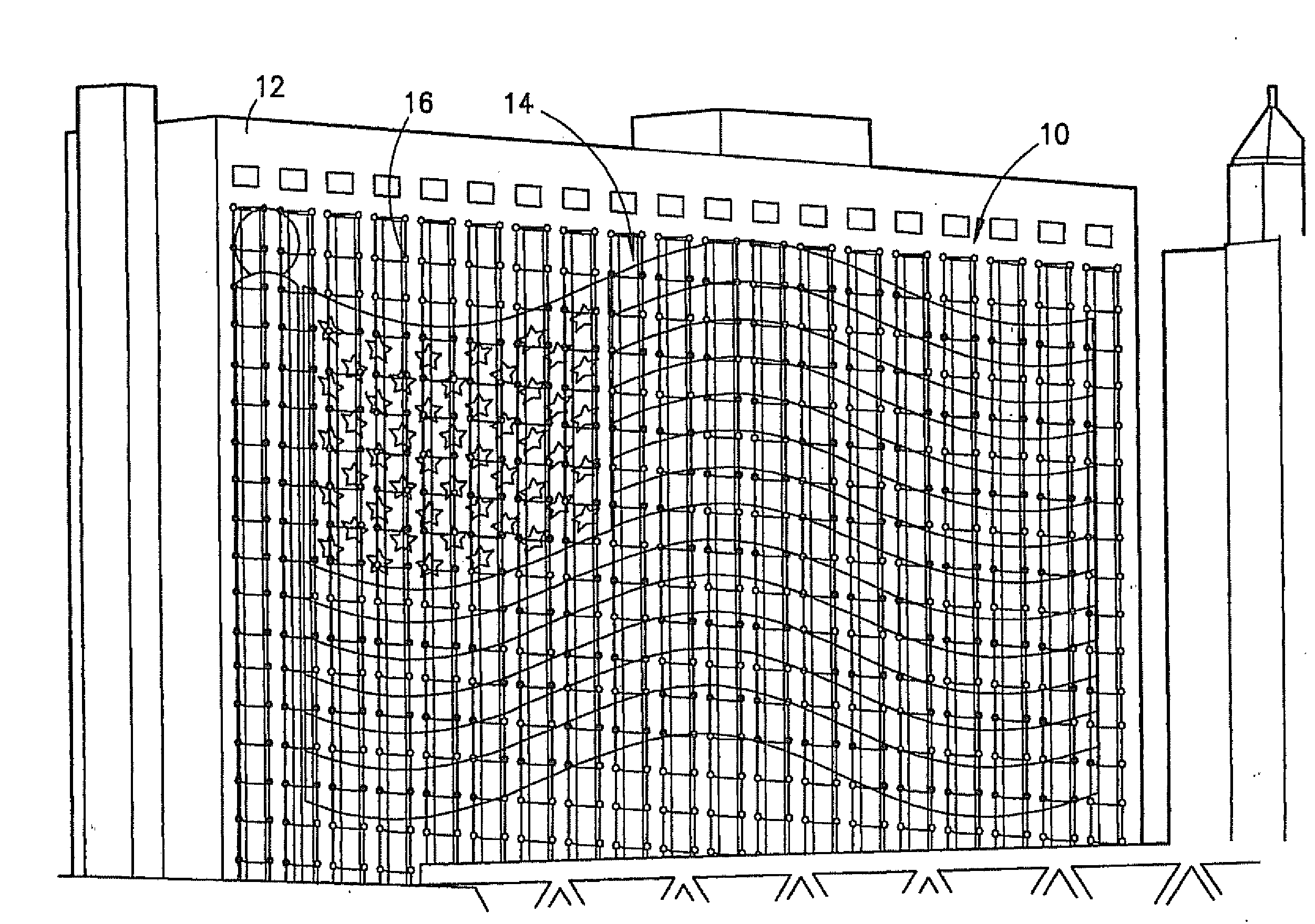
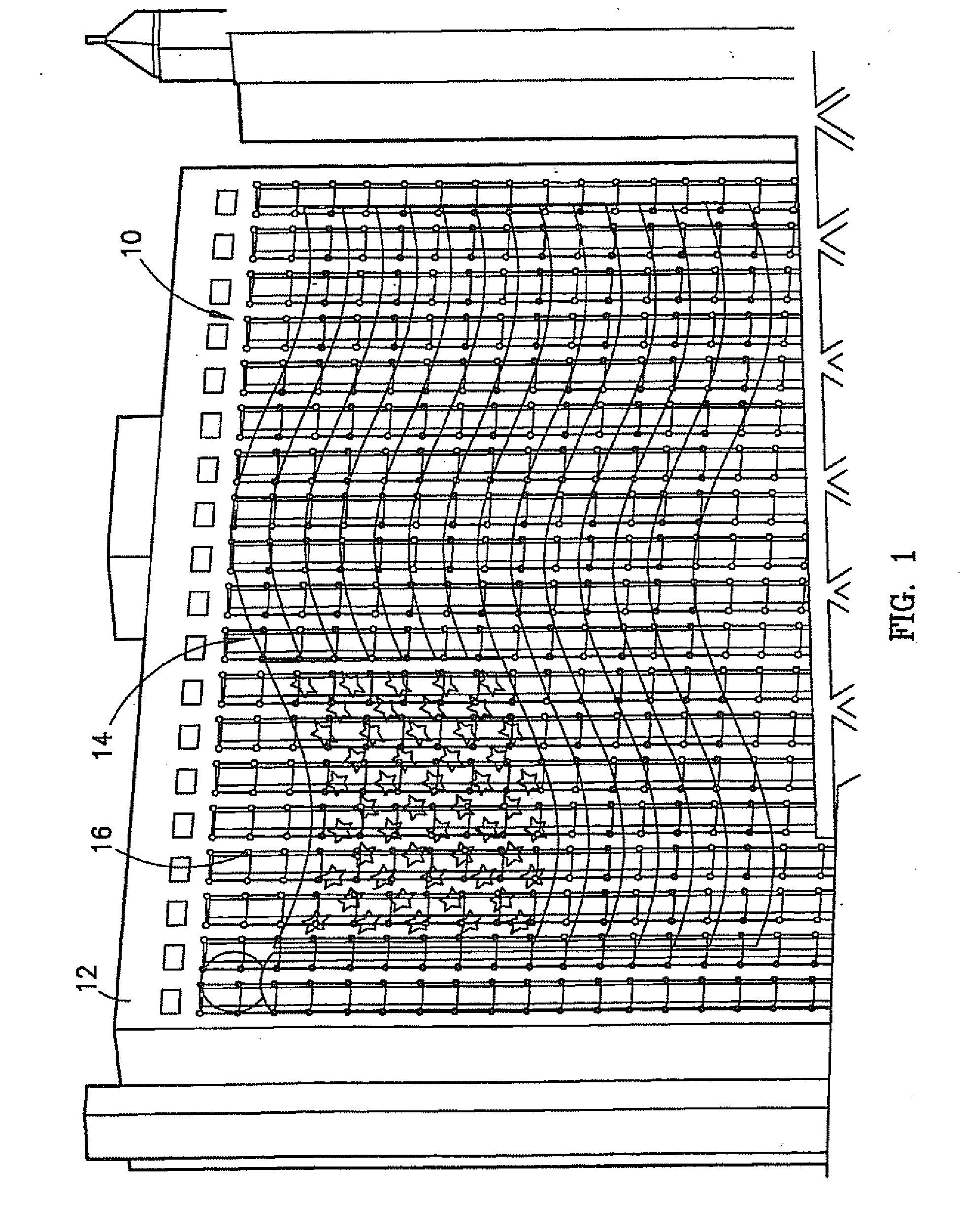
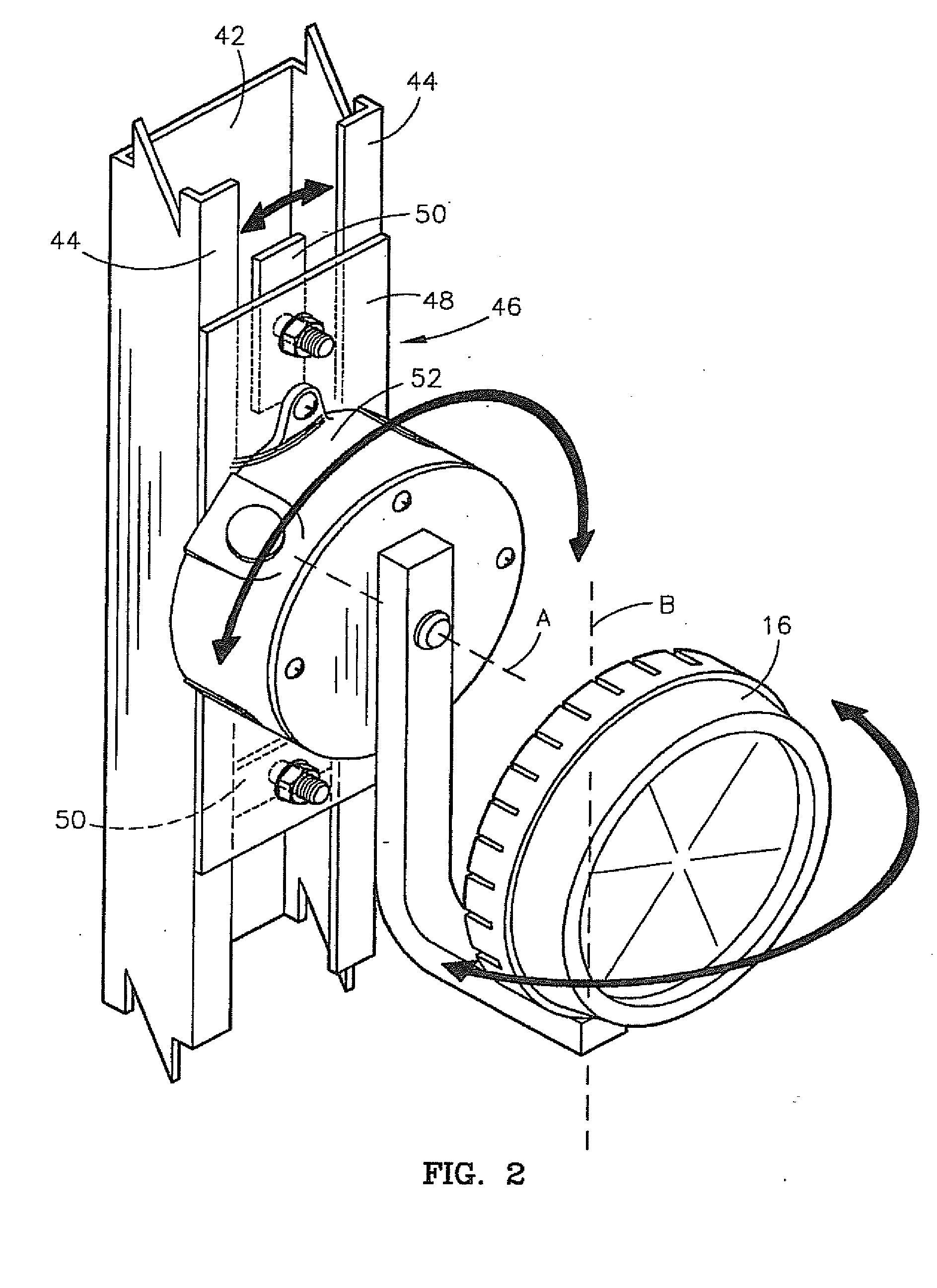
[0033]Turning now to the drawing figures, and particularly FIGS. 1-3, an expanded bit map display (“EBMD”) 10 and a method of creating such for mounting on a building surface 12 is shown. The EBMD or “display”10 is a graphical image 14 of an animated picture, a scrolling text, or other light-driven show. The display 10 comprises a plurality of arranged light fixtures 16 each representing a pixel. The light fixtures 16 are individually mounted to, secured to, or otherwise coupled with the building surface 12, such as an outside face or an internal wall of a building. The light fixtures 16 may then be instructed to display the graphical image 14, as discussed in more detail below. The invention is particularly adapted for placement of the EBMD 10 on irregular surfaces, wherein the surface provides or has associated with it a plurality of obstructions, protrusions, or other irregularities 18, such as windows, columns, lettering, air vents or grates, pipes, and / or other structural and a...


PUM


Abstract

An expanded bit map display (“EBMD”) (10) for displaying an image (14) and a method of creating such for mounting the EBMD (10) to a building surface (12) is provided. The EBMD (10)is a large-scale colored light display comprising a plurality of light fixtures (16) mounted to the building surface (12). The building surface (12) may include a plurality of irregularities (18) that interferes with the uniformity of a substrate (36) of the building surface (12). The method broadly comprises the steps of (a) selecting the building surface on which to locate the display (20); (b) selecting at least one graphical image to be displayed (22), such as an animated picture or scrolling text; (c) selecting a type of light fixture to mount to the surface (24); (d) determining a plurality of locations on the surface where a plurality of light fixtures can be mounted (26); (e) selecting from the plurality of locations where the light fixtures can be mounted a plurality of optimal locations at which to mount the light fixtures for producing the selected image (28); (f) mounting the light fixtures to the surface (30); (g) assigning lighting characteristics to each light fixture (32); and (h) determining an angular orientation of each light fixture for optimal viewing of the image from a pre-determined vantage point (34).

Description

RELATED APPLICATIONS[0001]This application is a divisional application of U.S. patent application Ser. No. 10 / 848,222, filed on May 18, 2004. The disclosure of the aforementioned application is hereby incorporated by reference in its entirety.BACKGROUND OF THE INVENTION[0002]1. Field of the Invention[0003]The present invention relates to light displays for displaying an image or a sequence of images on buildings or other surfaces. More particularly, the invention relates to a large-scale light display for mounting on a building surface comprising a plurality of light fixtures mounted directly to the building surface or via a mounting assembly. The light display is then operable to display an image or a sequence of images as a static or an animated image.[0004]2. Description of the Prior Art[0005]Large-screen colored light display systems have become very popular and can be found everywhere from sports arenas to outdoor commercial venues, such as Times Square in New York City. These ...

Claims


Application Information

Patent Timeline
Patent Type & Authority Applications(United States)
IPC IPC(8): G09G3/00F21V21/00G06F3/14G09F19/22G09G5/00H05B37/02
CPCG06F3/1446G09F9/33H05B37/029G09F19/22H05B37/0254G09F13/22H05B47/18H05B47/155
Inventor CALLEGARI, MARK R.GASSMAN, MICHAEL J.
Owner FLEXTRONICS IND
Learn More