Image orientation correction method and system

a technology of image orientation and correction method, applied in the field of image orientation, can solve problems such as the likely tilt of the camera mounted on the weapon

Inactive Publication Date: 2009-02-12
OPTECH VENTURES
View PDF13 Cites 164 Cited by
  • Summary
  • Abstract
  • Description
  • Claims
  • Application Information

AI Technical Summary

Problems solved by technology

In the case of urban warfare, however, the space separating friendly from enemy forces compresses from thousands of meters in open battle to only tens of meters in an urban environment of densely aggregated buildings, streets, and back all

Method used


Image

  • Image orientation correction method and system
  • Image orientation correction method and system
  • Image orientation correction method and system

Examples


Embodiment Construction

[0031]For purposes of this disclosure and for interpreting the claims, the following definitions are adopted. The term “image sensor” refers to an apparatus that detects energy in the near infrared, infrared, visible, and ultraviolet spectrums to be used for the formation of a displayed image based on the detected energy. The term “image sensor” may also refer to an apparatus that detects energy in the radio frequency spectra below optical frequencies, including, but not limited to, microwave, millimeter wave and terahertz radiation. The term “image sensor” may also refer to an apparatus that detects energy in other forms, such as sonar, for the formation of a displayed image. The detected energy may be used to form a single static image or a series of images (such as from a video camera) that may provide a moving image. The apparatus may comprise conventional optical sensing devices such a charge-coupled detector (CCD) or CMOS cameras, tube-based cameras or other optical sensors th...


PUM


Abstract

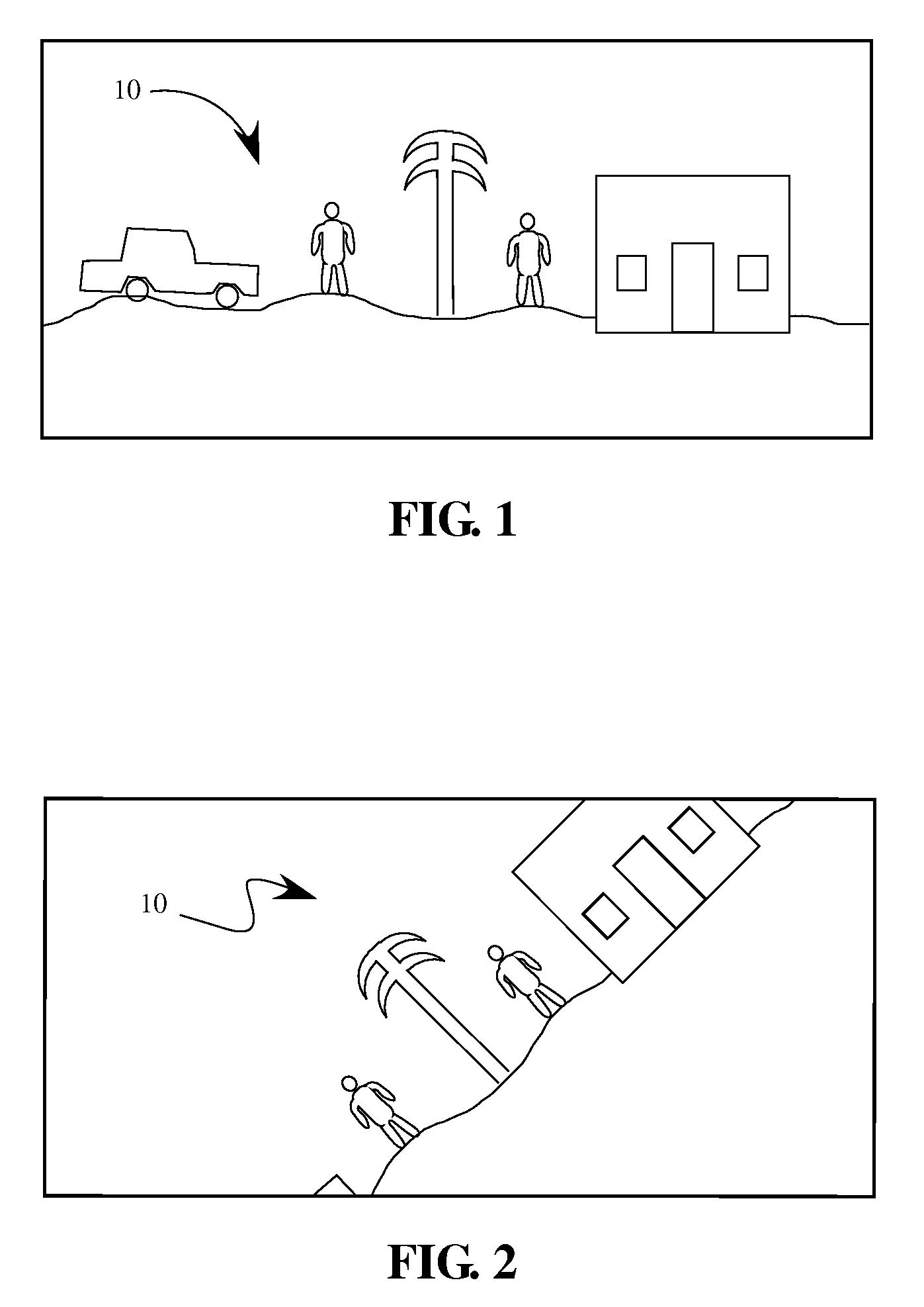
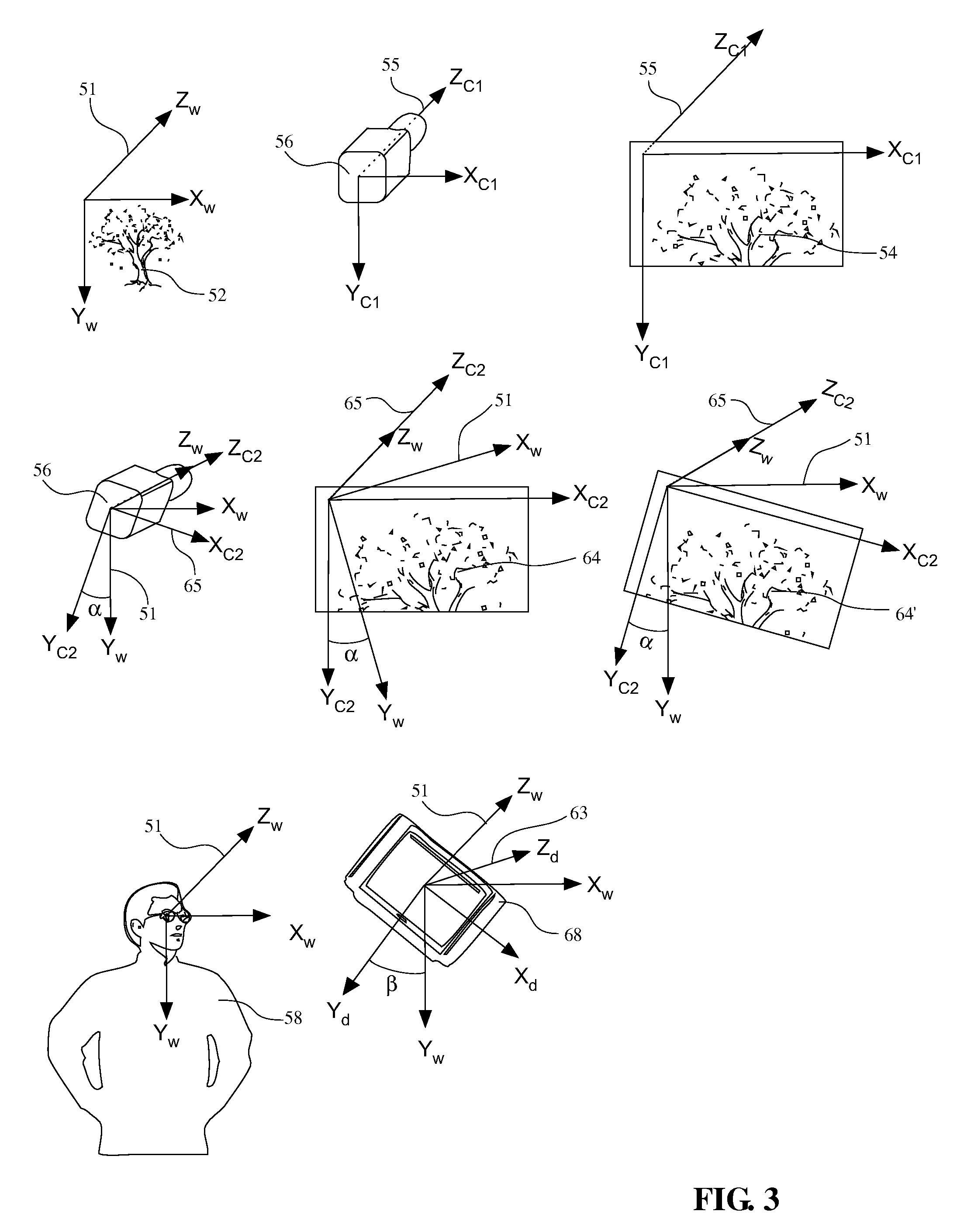
A system for correcting the rotational orientation of a targeting area provided by a weapon-mounted image sensor and an orientation sensor that detects the rotational orientation of the weapon. Measurements from the orientation sensor are used to transform the image data obtained from the image sensor into a desired rotational orientation. The transformed image data can then be displayed on a display in an orientation where objects having a vertical extent are displayed generally vertically.

Description

GOVERNMENT LICENSE RIGHTS[0001]This invention was made with Government support under contract number NBCHC060083 from DARPA / DOI. The Government has certain rights in this patent.1. FIELD[0002]This disclosure relates to the field of correcting the orientation of a displayed image.2. GENERAL BACKGROUND[0003]Long term efforts to increase the effectiveness of the individual warfighter have centered mostly on the precision, range, and versatility of small arms. In the case of urban warfare, however, the space separating friendly from enemy forces compresses from thousands of meters in open battle to only tens of meters in an urban environment of densely aggregated buildings, streets, and back alleys. Further, the urban warfare environment may increase the exposure of the warfighter to weapon fire from multiple directions, even though the urban environment may also provide the warfighter an increased ability to find cover. Hence, it would be desirable for the urban warfighter to make use ...

Claims


Application Information

Patent Timeline
IPC IPC(8): H04N7/18G06K9/32
CPCF41G3/165G02B27/0068G02B23/12F41G3/225F41G3/16
Inventor TEMOVSKIY, IGOR
Owner OPTECH VENTURES
Why Eureka
Try Eureka