
Communication device and communication method

a communication device and communication method technology, applied in the field of communication devices, can solve the problems of not performing a transmission process, difficult to achieve low power consumption,

Inactive Publication Date: 2009-02-12
PIONEER CORP
View PDF18 Cites 70 Cited by
  • Summary
  • Abstract
  • Description
  • Claims
  • Application Information

AI Technical Summary

Benefits of technology

[0011]The problem to be solved by the present invention includes cases, as examples, where the sleep mode may be deactivated by an unnecessary signal and the STA cannot sometimes recognize the presence of BSS managed by the AP.
[0012]To solve the above problems and to achieve the object, a communication device according to the invention set forth in claim 1 functions as an access point in a radio communication system and notifies presence of a network to each station (STA) in the radio communication system. The communication device includes a control unit that controls setting of an operating mode (a normal operation mode and a power-saving operation mode); a timer that determines a transmission period of a beacon for notifying the presence of the network; and a beacon transmitting unit that transmits a beacon based on the transmission period. When the control unit instructs to switch from the normal operation mode to the power-saving operation mode, the timer sets the transmission period of the beacon to be longer than a transmission period in the normal operation mode.
[0013]Furthermore, a communication device the invention set forth in claim 4 functions as an access point in a radio communication system and notifies presence of a network to each station (STA) in the radio communication system. The communication device includes a control unit that controls setting of an operating mode (a normal operation mode and a power-saving operation mode); a timer that determines a transmission period of a beacon for notifying the presence of the network; a beacon transmitting unit that transmits a beacon based on the transmission period; and a sleep control unit that sets all circuits (including the control unit and the beacon transmitting unit), except for the timer, related to data transmission/reception to be in a sleep state (power-supply stopped state) when the control unit instructs to switch from the normal operation mode to the power-saving operation mode. During operation in the power-saving operation mode, the timer notifies the sleep control unit of a wake-up request at a timing earlier than a transmission timing of a beacon by a first time, and further notifies the sleep control unit of a sleep request after a second time has passed from the transmission timing of the beacon, and when receiving the wake-up request, the sleep control unit supplies power to a circuit related to a reception process ...

Problems solved by technology

Therefore, it is difficult to achieve low power consumption.
Furthermore, the AP does not also perform a transmission process in the sleep mode.

Method used


Image

  • Communication device and communication method
  • Communication device and communication method
  • Communication device and communication method

Examples


first embodiment

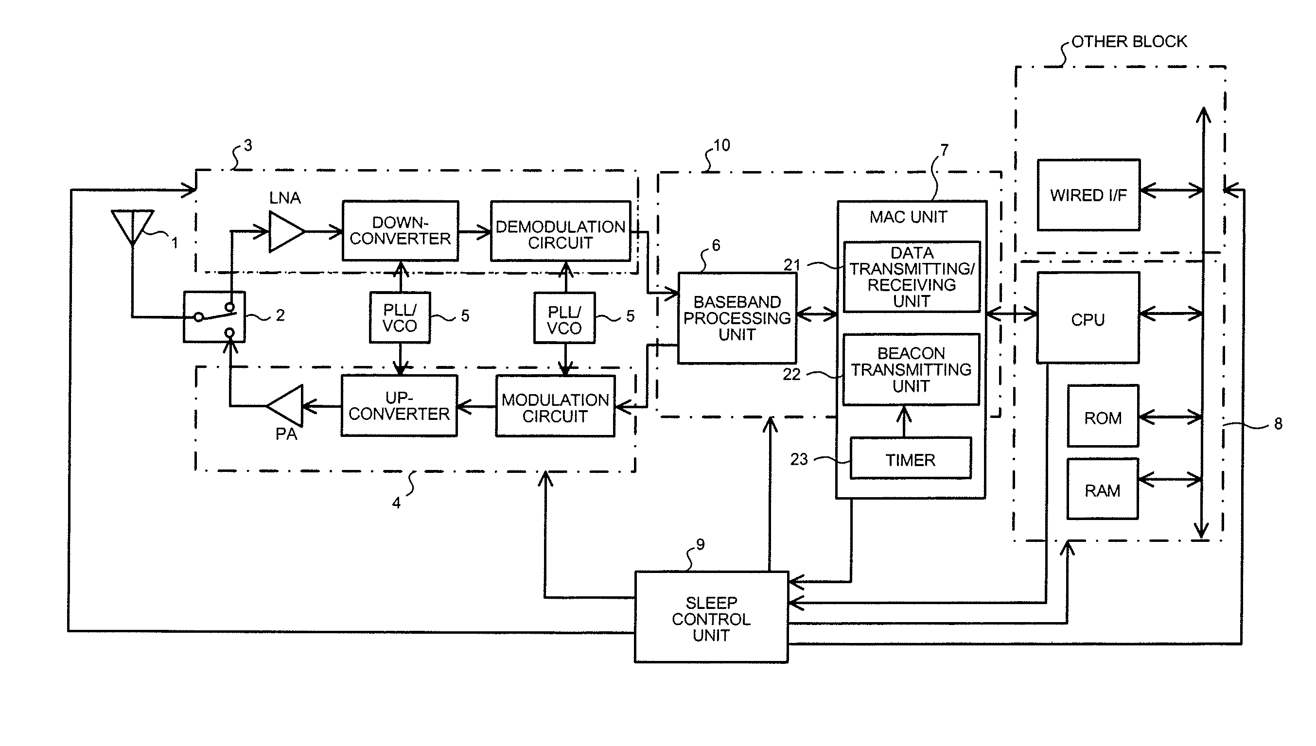
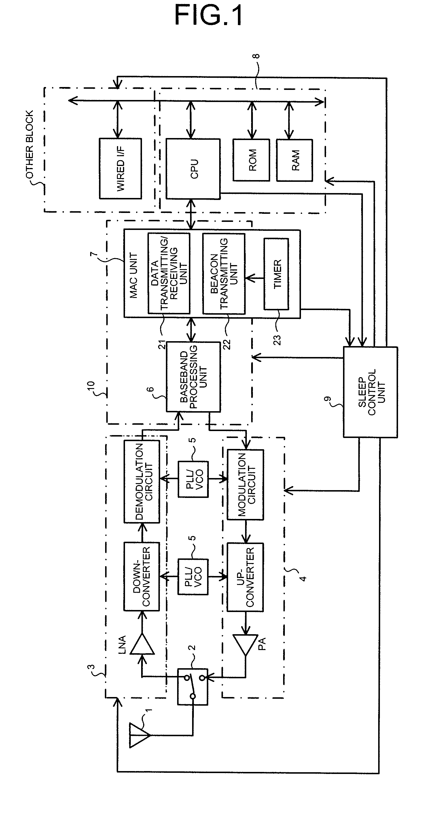
[0049]FIG. 1 is a diagram of an example of the configuration of an access point (AP), according to a first embodiment, which functions as the communication device of the present invention. The AP includes an antenna 1, a selector switch 2 for transmission / reception, a reception processing unit 3 that performs a predetermined reception process; a transmission processing unit 4 that performs a predetermined transmission process, a PLL / VCO 5 that supplies clock to the reception processing unit 3 and the transmission processing unit 4, a baseband processing unit 6 that performs a predetermined baseband process, a MAC unit 7 that includes a data transmitting / receiving unit 21, a beacon transmitting unit 22, and a timer 23 which determines a beacon transmission period; a control unit 8 that includes a CPU that controls a communication method (method of setting an operating mode (normal operation mode, power-saving operation mode)) according to the first embodiment in the AP, a ROM that st...

second embodiment

[0078]FIG. 6 is a diagram of an example of the configuration of an access point (AP), according to a second embodiment, which functions as the communication device according to the present invention. The same reference numerals are assigned to those corresponding to the components of the first embodiment, and the explanation thereof is omitted. In the present embodiment, only components and processes different from these of the first embodiment are explained below.

[0079]In addition to the antenna 1, the selector switch 2, the reception processing unit 3, the transmission processing unit 4, the PLL / VCO 5, and the baseband processing unit 6 according to the first embodiment, the AP of the present embodiment includes a MAC unit 7a that includes a timer 23a which determines a beacon transmission period (which does not determine a timing of notifying a wake-up request and a sleep request, unlike the first embodiment); and a control unit 8a that includes a CPU which controls a communicati...

third embodiment

[0085]The process of a third embodiment is explained below. It is noted that the configuration of the AP according to the third embodiment is the same as that of FIG. 6 according to the second embodiment. In the present embodiment, only the process different from that of the first embodiment or the second embodiment is explained.

[0086]The AP of the third embodiment causes the MAC unit 7a to stop transmitting the beacon in the power-saving operation mode. Namely, in this case, the operation of the timer 23a is stopped. On the other hand, if a new STA participates in the BSS, the operation of the timer 23a is restarted. It is noted that the power supply state in the power-saving operation mode is the same as that in the normal mode, and thus the power is supplied to the reception processing unit 3 and the baseband block 10a.

[0087]In the present embodiment, the STA has the configuration as follows. FIG. 9 is a diagram of an example of the configuration of a station (STA) according to ...


PUM


Abstract

A control unit controls setting of an operating mode. A timer determines a transmission period of a beacon for notifying presence of a network. A beacon transmitting unit transmits a beacon based on the transmission period. When the control unit instructs to switch from a normal operation mode to a power-saving operation mode, the timer sets a transmission period of the beacon to be longer than a transmission period in the normal operation mode.

Description

TECHNICAL FIELD[0001]The present invention relates to a communication device that functions as an access point or a station that configures a radio communication system.BACKGROUND ART[0002]There are systems that are commercialized in recent years, in which TV broadcasting or analog video signals are A / D-converted, and signals are digitally transmitted by radio so that the TV broadcasting is viewed by a monitor. In the above systems, a data transmitter functions as an access point (AP), and a monitor functions as a station (STA).[0003]The operations of the AP and the STA in the system are briefly explained below. At first, the AP periodically transmits a beacon when power is on, and waits for an association from the STA. On the other hand, the STA detects the beacon to thereby recognize the presence of the AP, and transmits an association signal to the AP to promote the registration of the own device. Thereafter, the STA transmits a signal to request the start of transmission of desi...

Claims


Application Information

Patent Timeline
IPC IPC(8): G08C17/02H04B1/40H04W52/02H04W84/12
CPCH04W48/08Y02B60/50H04W52/0216Y02D30/70
Inventor USUBA, HIDEMI
Owner PIONEER CORP
Learn More