Ground anchor

a technology of ground anchors and anchors, applied in the field of ground anchors, can solve the problems of soil retaining mat damage, and mat weakening, and achieve the effect of reducing the tendency to damage and improving utility

Inactive Publication Date: 2009-02-12
MACLEAN POWER LLC
View PDF10 Cites 27 Cited by
  • Summary
  • Abstract
  • Description
  • Claims
  • Application Information

AI Technical Summary

Benefits of technology

[0014]It is therefore an object of the invention to provide a ground anchor having improved utility for use with mat structures having leading edge surfaces having a reduced tendency to damage the mat during driving of the anchor through the mat structure.

Problems solved by technology

However, the chiseled or sharpened leading edges which facilitate penetration into the ground can, in certain instances, cause damage to certain types of soil retaining mats which are commonly used in turf reinforcement and ground stabilization.
Where it is desired to anchor such mats to the underlying soil, the use of the previously known driven pivoting anchors can cause damage to the mat, particularly since the chiseled or sharpened leading edges will have a tendency to cut through the material of the mat, thereby weakening the mat.

Method used


Image

  • Ground anchor
  • Ground anchor
  • Ground anchor

Examples


Embodiment Construction

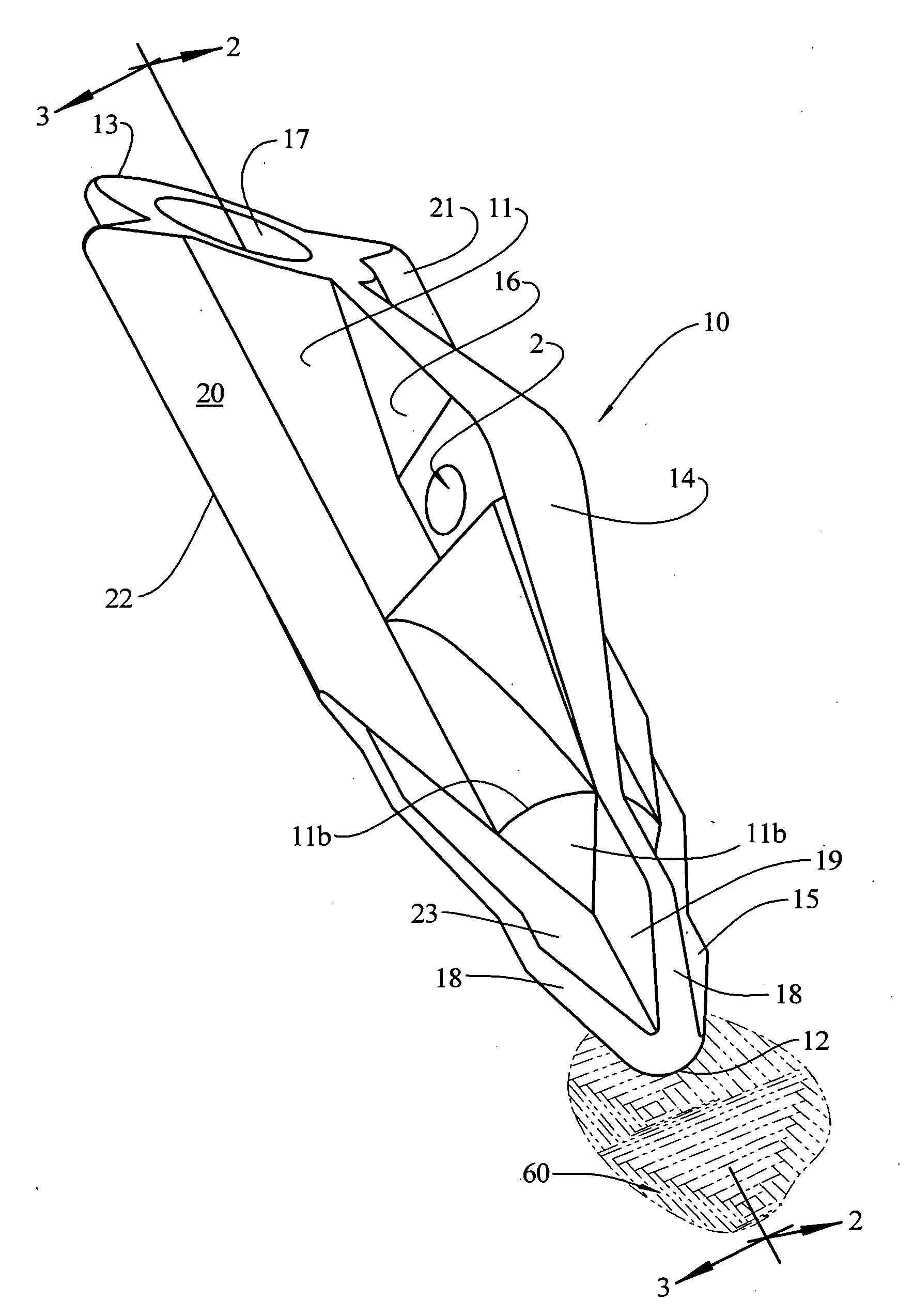
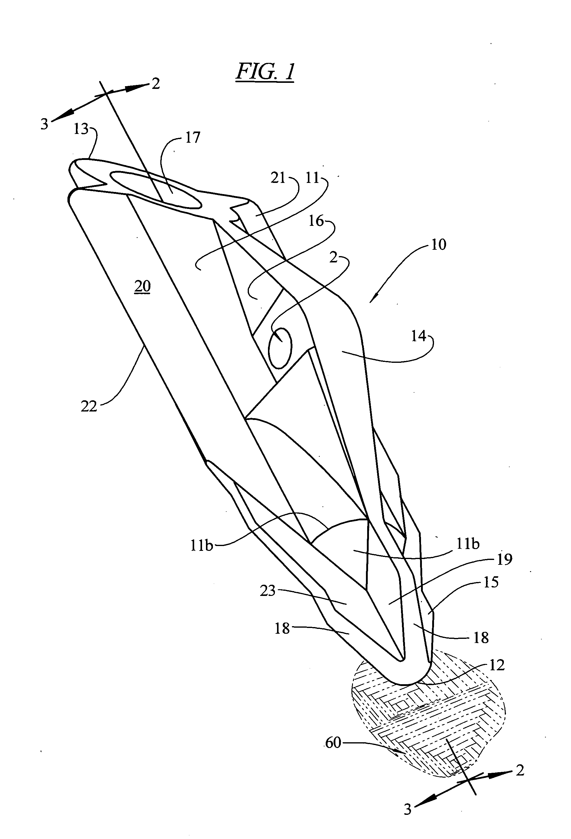
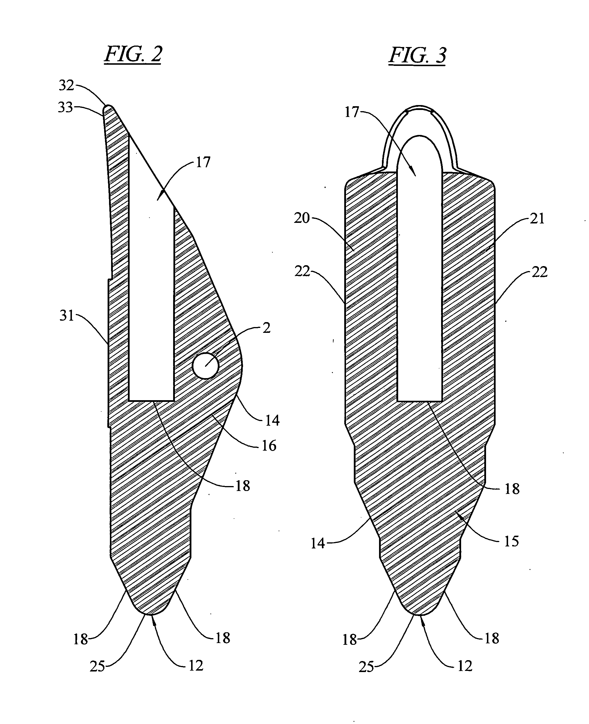
[0020]FIG. 1 illustrates a ground or earth anchor 10 of the type often referred to as a driven and rotating or pivoting anchor in that the anchor is driven into the ground by force and after having being driven to the desired depth, a cable or rod attachment member attached to the anchor is pulled in a direction to withdrawal the anchor from the ground. Because of the design of the anchor and the position of the attachment of the cable or pulling rod to the anchor, the pulling of the anchor by the attachment member causes the anchor to undergo a pivoting or rotation in the ground towards a final position in which the longitudinal axis of the anchor is positioned more towards a position normal to the pulling cable or rod.

[0021]Such anchors often include a main body section 11, which may be generally cylindrically formed (other shapes are known in the art, including rectangular and oval), a leading edge 12, a trailing edge 13, a raised section 14 having means 2 for attachment of a cab...


PUM


Abstract

An earth anchor of the pivoting type having an essentially cylindrical body, a blind bore extending thereinto from a trailing axial end of the cylindrical body and a leading edge projecting from a leading end of the body, the leading edge being formed as a rounded surface adapted for penetration through reinforcement paths while minimizing severing of the strands of the mat.

Description

BACKGROUND OF THE INVENTION[0001]1. Field of the Invention[0002]This invention relates to ground anchors, and more specifically to driven pivoting ground anchors.[0003]2. General Background[0004]Ground anchors, or earth anchors, of the driven and pivoting or tilting type are well known and generally include a main body portion having a leading edge adapted to be driven into the ground, a trailing edge including an outturned lip and a cable or rod or guide wire attachment point intermediate the leading and trailing edges generally positioned from about the midpoint of the overall length of the anchor or towards the trailing edge so that upon exertion of the force on the cable or attached rod or guide wire, after insertion of the anchor into the ground, the trailing edge's outturned lip will bite into the earth, causing the anchor to rotate or pivot to a locked position generally at a right angle to the withdrawal force.[0005]Widely currently used driven pivoting anchors of the type d...

Claims


Application Information

Patent Timeline
Patent Type & Authority Applications(United States)
IPC IPC(8): E02D17/20E21D20/00
CPCE02D17/20E02D5/803
Inventor STAHM, WILLIAM G.
Owner MACLEAN POWER LLC
Why Eureka
Try Eureka