
Autonomous device with biofouling control and method for monitoring aquatic environment

a technology of autonomous devices and aquatic environments, applied in the direction of instruments, liquid displacement, separation processes, etc., can solve the problems of biofouling prevention for sensor systems, biofouling remains a major problem that to date has not been adequately addressed, and the toxicity of fouling paints is extrem

Active Publication Date: 2009-02-12
UNIVERSITY OF MARYLAND CENTER FOR ENVIRONMENTAL SCIENCE
View PDF2 Cites 26 Cited by
  • Summary
  • Abstract
  • Description
  • Claims
  • Application Information

AI Technical Summary

Benefits of technology

[0011]It is therefore an object of the present invention to provide an extended deployment for devices monitoring aquatic environments with anti-fouling capabilities incorporated in the device.
[0012]It is another object of the present to provide a monitoring device with biofouling control for extended time operation in aquatic environments which is either preprogrammed prior to deployment or is controlled / re-programmed during the deployment from a remote host computer to perform sensor sampling cycles in which the sensor instrument samples the aquatic environment of interest for data acquisition. Subsequent to the sampling being completed, the sensor instrument is surrounded with a biocide anti-fouling environment to destroy and remove the fouling organisms from the environment immediately surrounding the sensor instrument.
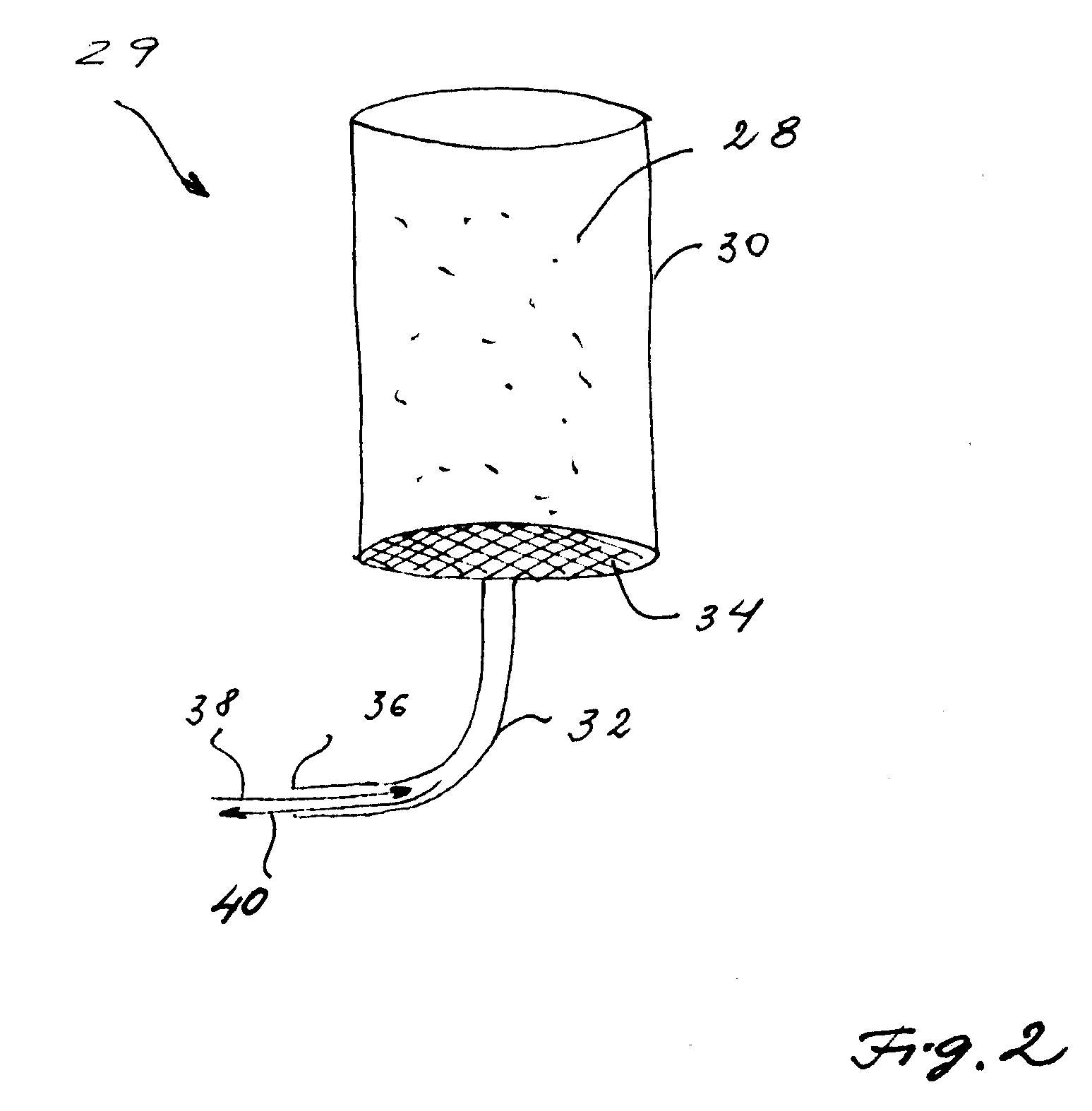
[0019]The sensor envelope is preferably formed as a housing with one or several windows which are controllably opened / closed in accordance with the sampling cycle of the sensors. The housing may be implemented as a double-wall structure having an outer cup and an inner cup positioned in concentric relationship each with the other and each having a plurality of openings of predetermined dimensions, and positioned at predetermined positions on the walls of the inner and outer cups. The controller changes a relative disposition between the inner and outer cups in synchronism with the sampling cycle of the sensors in order to control the relative disposition between the openings on the walls of the inner and outer cups, thereby controlling the extent of “openness / closeness” of the chamber to the aquatic environment.

Problems solved by technology

However, biofouling remains a major problem that to date has not been adequately addressed.
Biofouling is, for a large percentage of instrumentation deployments, the single biggest factor affecting the operation, maintenance and data quality of in-water monitoring sensors, and therefore biofouling prevention for sensor systems is considered a major issue in aquatic environment monitoring.
However, the anti-fouling paints are extremely toxic and thus are harmful for living organisms, while wipers do not have the capability of complete prevention and removal of bio-fouling, thereby only partially addressing the bio-fouling problem.
Such wipers also require additional energy consumption that is undesirable in autonomous devices.
This is a time and cost consuming endeavor which makes aquatic environments monitoring extremely expensive and labor intensive.

Method used


Image

  • Autonomous device with biofouling control and method for monitoring aquatic environment
  • Autonomous device with biofouling control and method for monitoring aquatic environment
  • Autonomous device with biofouling control and method for monitoring aquatic environment

Examples


Embodiment Construction

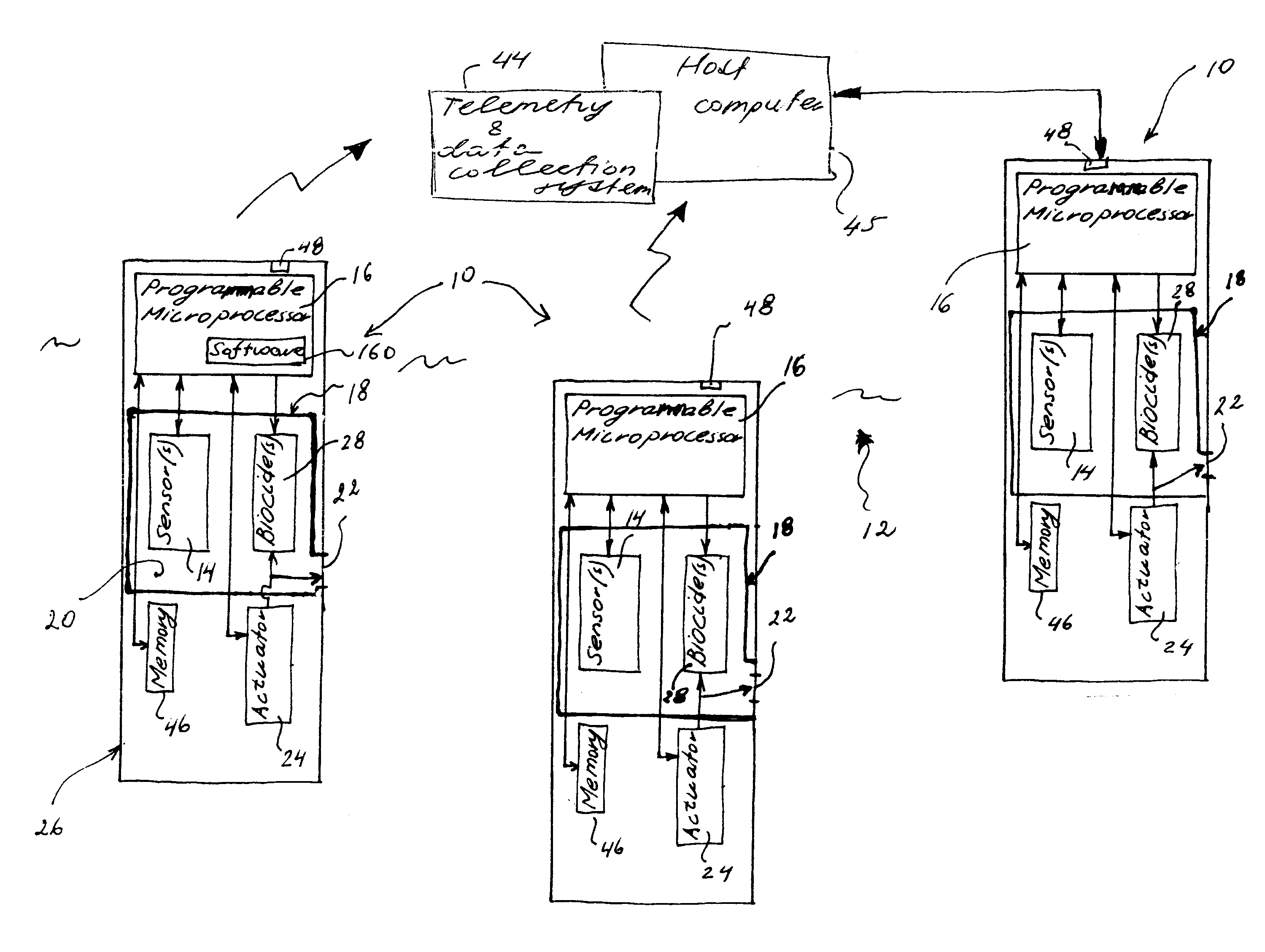
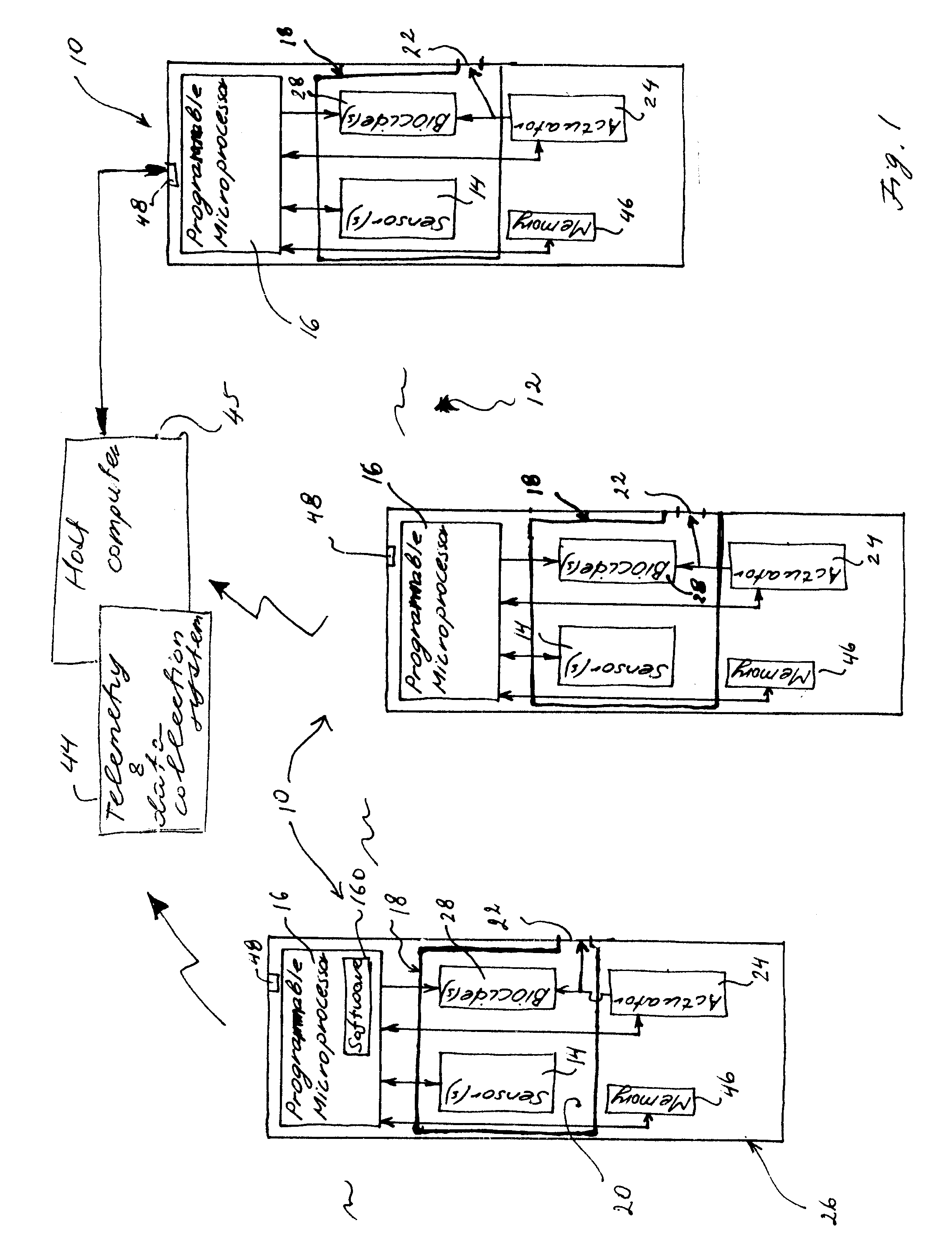
[0052]Referring to FIG. 1, a device 10 is shown with biofouling control for monitoring fluid environment (for example aquatic environment or gaseous environment) 12 is designed for deployment at a predetermined position in an aquatic environment for an extended period of time. Due to the anti-fouling control, the device 10 is capable of autonomous operation without the need for servicing more than once every two months.

[0053]The autonomous device 10 of the present invention may use any number of sensors 14 of a variety of types and is adapted to protect analog or serial sensors for measuring physical and chemical parameters of the water in the aquatic environment 12. As one of many possible examples, a multiprobe sensor instrument may be used with the autonomous device 10 of the present invention, such as multi-parameter Sondes YS16600 for monitoring dissolved oxygen, chlorophyll, blue-green algae, turbidity, temperature, pH level, etc., although other sensing arrangements are conte...


PUM

PropertyMeasurementUnit
Timeaaaaaaaaaa
Fouling propertiesaaaaaaaaaa

Abstract

The device with biofouling control for monitoring aquatic (or gaseous) environment encloses an environmental sensor instrument in a sensor chamber which programmably opens for allowing direct communication between the sensors and the water of interest for sampling and which is closed after the sampling sequence is completed to create an anti-fouling environment in the sensor chamber by adding a biocide into the chamber and exposing the sensors to the anti-fouling environment for a predetermined period of time. The monitoring device includes a microprocessor which is preprogrammed prior to deployment of the device (and which may be re-programmed from a remote host computer during the deployment) into the aquatic environment and which controls the operation of the entire device for a long deployment (up to several months). The opening / closing of the sensor housing, instrument sampling and release of the biocide into the chamber are synchronized to provide the most effective sampling / anti-fouling sequence of operations of the autonomous device.

Description

REFERENCE TO RELATED APPLICATIONS[0001]The present Utility Patent Application is based on the Provisional Patent Application 60 / 954,412 filed 7 Aug. 2007.FIELD OF THE INVENTION[0002]The present invention is directed to the monitoring of fluid (aquatic and gaseous) environments, and more in particular to devices with anti-biofouling capabilities deployed in aquatic environment for acquisition of data related to chemical and physical conditions of the environment of interest.[0003]In overall concept, the present invention is directed to biofouling control in device monitoring an aquatic environment by means of periodically exposing the deployed environmental sensor(s) to a biocide environment after sampling sequence is completed by the sensor(s), thereby protecting the immediate surrounding of the sensors from biofouling formation.[0004]The present invention is further directed to an autonomous device which is preprogrammed prior to deployment in an aquatic environment of interest to ...

Claims


Application Information

Patent Timeline
IPC IPC(8): A61L2/16B01J19/00
CPCG01N1/18G01N1/2035G01N21/15G01N2035/00881G01N2001/021G01N2015/0088G01N33/18G01N2015/019
Inventor KELLY, VINCENT M.CODISPOTI, LOUIS A.HARFORD, JAY
Owner UNIVERSITY OF MARYLAND CENTER FOR ENVIRONMENTAL SCIENCE
Learn More