Method for Selecting Antennas in a Wireless Networks

a wireless network and antenna technology, applied in the direction of digital transmission, substation equipment, transmission path sub-channel allocation, etc., can solve the problems of limiting the universal application of mimo technique, power consumption and component size at the transceiver, and high cost of rf chain of mimo system,

Active Publication Date: 2009-02-12
MITSUBISHI ELECTRIC RES LAB INC
View PDF9 Cites 134 Cited by
  • Summary
  • Abstract
  • Description
  • Claims
  • Application Information

AI Technical Summary

Benefits of technology

[0019]Level-B signaling is used to provide antenna selection parameters to the UE transceiver using, for example, network layer three radio resource control (RRC) messages, and possibly the request to start or stop antenna selection.

Problems solved by technology

While MIMO systems perform well, they may increase the hardware cost, signal processing complexity, power consumption, and component size at the transceivers, which limits the universal application of MIMO technique.
In particular, the RF chains of MIMO systems are usually expensive.
In addition, the signal processing complexity of some MIMO methods also increases exponentially with the number of antennas.
While the RF chains are complex and expensive, antennas are relatively simple and cheap.

Method used


Image

  • Method for Selecting Antennas in a Wireless Networks
  • Method for Selecting Antennas in a Wireless Networks
  • Method for Selecting Antennas in a Wireless Networks

Examples


Embodiment Construction

[0033]LTE System Overview

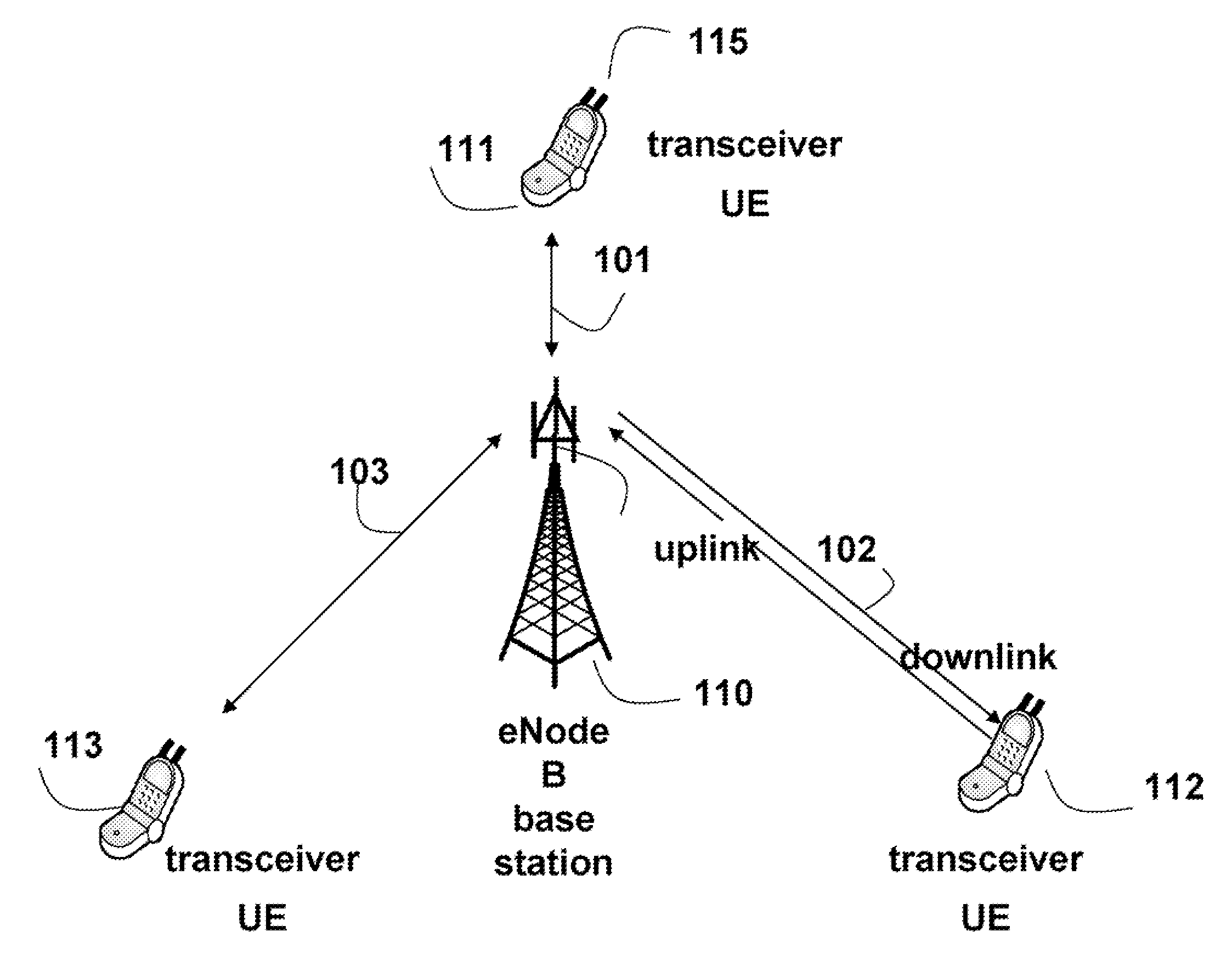
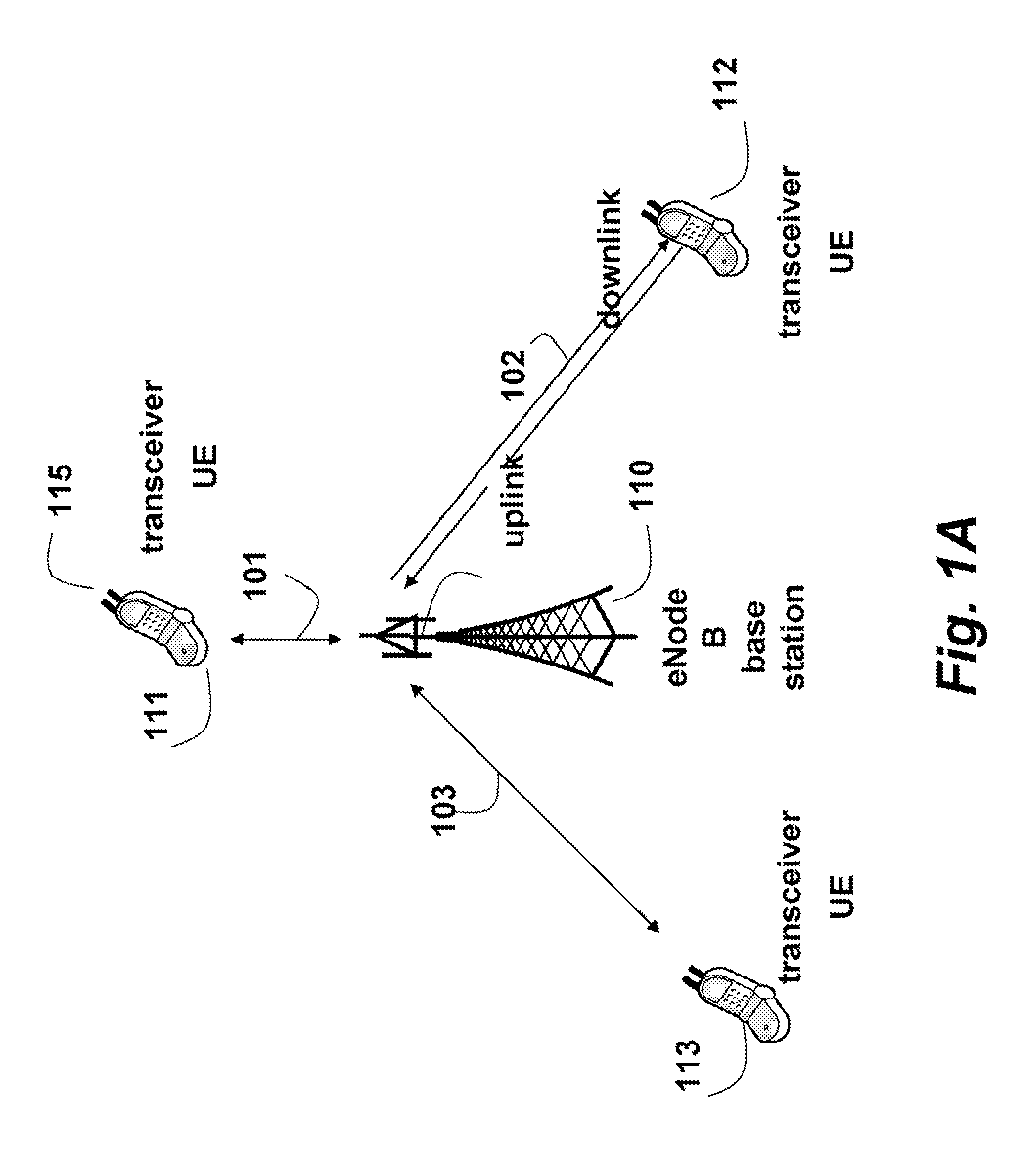
[0034]FIG. 1 shows the general structure of an OFDMA 3GPP LTE wireless network according to an embodiment of the invention. Multiple user equipments (UEs) or transceivers 111-113 communicate with a base station 110. It should be understood that the base station also operates as a transceiver. However, hereinafter, reference to transceivers means UE, unless specified otherwise. It should be noted that invention can also be used with SC-FDMA and OFDM networks.

[0035]The base station is called an evolved Node B (eNodeB) in the 3GPP LTE standard. The eNodeB 110 manages and coordinates all communications with the transceivers in a cell using connections 101, 102, 103. Each connection can operate as a downlink from the base station to the UE or an uplink from the UE to the base station. Because the transmission power available at the base station is orders of magnitude greater than the transmission power at the UE, the performance on the uplink is much more critica...


PUM


Abstract

A method and system selects antennas in a wireless network including a base station and user equipment (UE) transceivers. The base station specifies times and frequencies to transmit sounding reference signals (SRSs), and antennas to use to transmit the SRSs for the specified times and frequencies. The transceivers transmit the SRS according to the specified times, frequencies, and antennas. The base station selects subsets of the set of available sets of antennas, and indicates the selected subset of antennas to the transceiver.

Description

FIELD OF INVENTION[0001]This invention relates generally to antenna selection in wireless networks, and more particularly to selecting antennas in wireless networks.BACKGROUND OF THE INVENTION[0002]OFDM[0003]Orthogonal frequency division multiplexing (OFDM) is a multi-carrier communication technique, which employs multiple orthogonal sub-carriers to transmit parallel data streams. Due to the relatively low symbol-rate on each of the sub-carriers, OFDM is robust to severe channel conditions, such as frequency attenuation, narrowband interference, and frequency-selective fading. By prepending a cyclic prefix (CP) in front of each symbol, OFDM can eliminate inter-symbol interference (ISI) when the delay spread of the channel is shorter than the duration of CP. OFDM can also simplify frequency-domain channel equalization because the multiple sub-carriers are orthogonal to each other to eliminate inter-carrier interference (ICI).[0004]OFDMA[0005]When OFDM is combined with a multiple acce...

Claims


Application Information

Patent Timeline
Patent Type & Authority Applications(United States)
IPC IPC(8): H04M1/00
CPCH04B7/0691H04B7/061H04L5/0051H04L5/0012
Inventor TEO, KOON HOOMEHTA, NEELESH B.TANG, JIAFUKUI, NORIYUKI
Owner MITSUBISHI ELECTRIC RES LAB INC
Why Eureka
Try Eureka