Scraper device, as well as construction machine

a technology of swivelling device and construction machine, which is applied in the direction of manufacturing tools, vehicle cleaning, and cleaning, etc., can solve the problems of high surface pressure, time-consuming bolt removal, and high surface pressure, and achieve the effect of low design height, large swivelling angle and low design height of swivelling devi

Active Publication Date: 2009-02-19
WIRTGEN AMERICA
View PDF7 Cites 6 Cited by
  • Summary
  • Abstract
  • Description
  • Claims
  • Application Information

AI Technical Summary

Benefits of technology

[0011]the use of bolts has the disadvantage of a small contact surface, which results in a high surface pressure and high wear and tear,
[0014]It is therefore an object of the invention to create a scraper device, the scraper blade of which is capable of swivelling with a large swivelling angle at a small swivelling radius, which realizes a low design height and does not require manual operation.
[0016]The invention thus provides that the swivelling device is provided with an operating device which is articulated, in a space-saving manner, at the upper end of the upper scraper blade between a permanently installed part of the construction machine and the upper part of the scraper blade. The operating device is therefore independent of lifting cylinders of the scraper blade and can swivel the scraper blade about a first swivelling axis when the scraper blade is disengaged from the lateral retaining devices. The arrangement of the operating device enables a large swivelling angle, since the scraper blade can be swivelled about 90° and more. A small swivelling radius is achieved at the same time because the lifting cylinders, and thus also the scraper blade itself, are not required to provide any additional lifting path for an additional swivelling movement even after completion of the actual lifting movement. A low design height of the swivelling device is realized in that the operating device is preferably arranged horizontally. In addition, swivelling of the scraper blade is effected fully automatically without requiring any manual operation.
[0019]The operating device at the upper part of the scraper blade engages with an articulation of the scraper blade below the swivelling axis. As the operating device engages with the upper part of the scraper blade below the swivelling axis, the swivelling device may be of especially compact design. For swivelling, the operating device presses against the scraper blade, so that the same can be swivelled about the swivelling axis.
[0023]The aforementioned features enable favourable leverage ratios and a small swivelling radius due to the fact that the two parts of the scraper blade are entirely moved together, and that a separate swivelling device is provided. In addition, a large swivelling angle of more than 90° is achieved simultaneously with a compact design.
[0029]The lower part is preferably raisable in relation to the upper part by means of a lifting device, until the lower part is disengaged from the lateral retaining devices. For swivelling of the scraper blade, the lower part of the scraper blade is raised until it has moved beyond the sliding blocks provided on both sides. When the scraper blade is moved back into the operating position, these steps are correspondingly carried out in the reverse sequence. In the process, the lower part of the scraper blade threads in again behind the two-sided sliding blocks. For this purpose, the guides of the scraper blade are provided with chamfers or roundings respectively, with the sliding blocks themselves being supported in a rotating fashion. This support also brings about an as large contact surface as possible and thus low surface pressures, which lead to low wear and tear.

Problems solved by technology

In summary, the known state of the art has the following disadvantages:Lifting cylinders simultaneously designed for lifting as well as for swivelling have a too large design height,the swivelling radius is larger with these solutions, which requires the rear travel drive units to be arranged far towards the rear,manual removal of the bolts is time-consuming and requires effort,if one of the bolts gets jammed, it needs to be removed manually using a tool, which involves a lot of effort,the use of bolts has the disadvantage of a small contact surface, which results in a high surface pressure and high wear and tear,the achievable swivelling angle is too small,the design height of single-part scraper devices is so large that it is suitable only where the milling drum is arranged at the rear end of the construction machine, and not between the front axle and the rear axle below the machine frame.
This support also brings about an as large contact surface as possible and thus low surface pressures, which lead to low wear and tear.

Method used


Image

  • Scraper device, as well as construction machine
  • Scraper device, as well as construction machine
  • Scraper device, as well as construction machine

Examples


Embodiment Construction

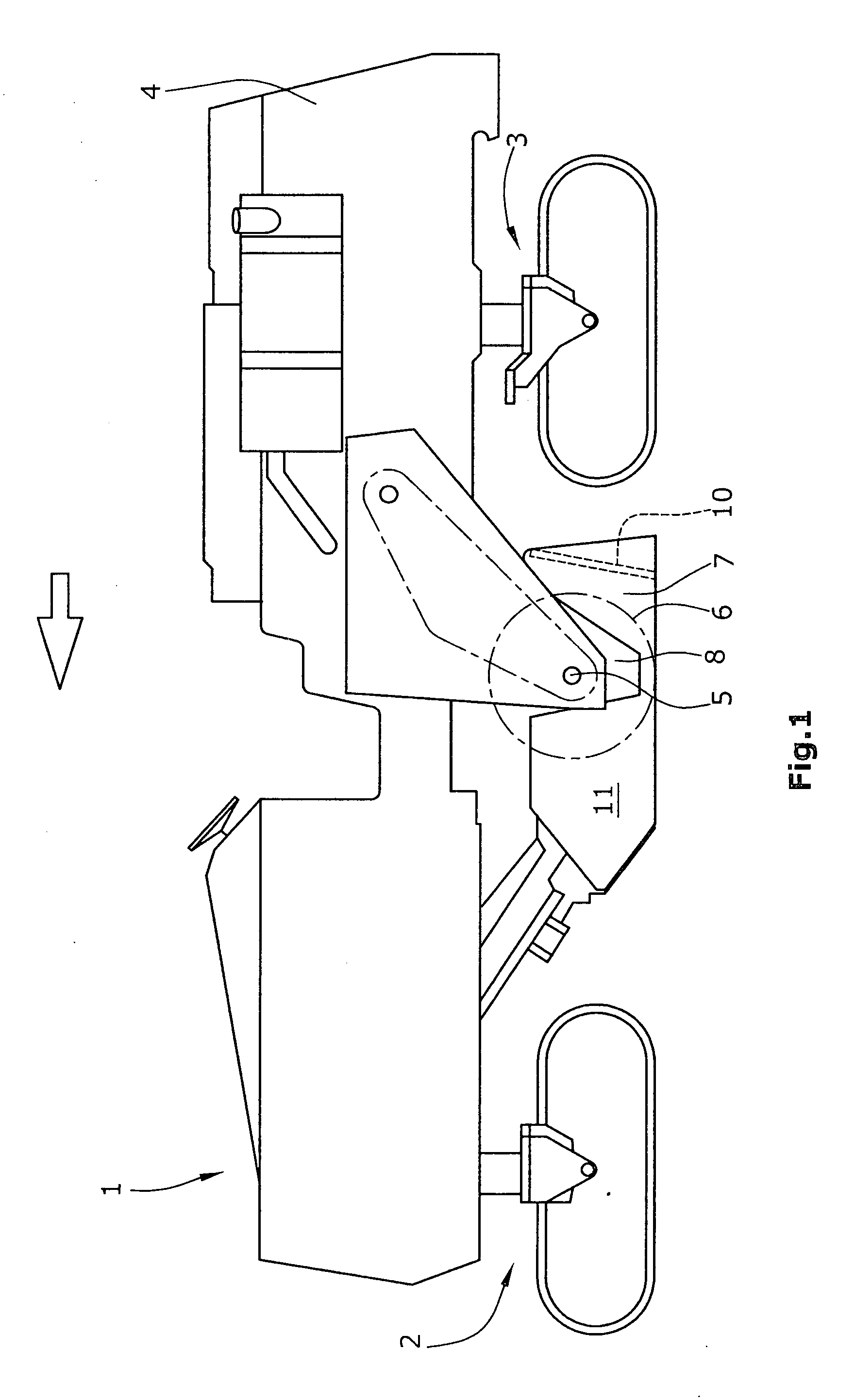
[0047]FIG. 1 shows an automotive road milling machine 1 in the design of a large milling machine, in which a milling drum 6 is mounted between front and rear travel drive units 2, 3 with a milling drum axis 5 in lateral walls 8 of the machine frame 4.

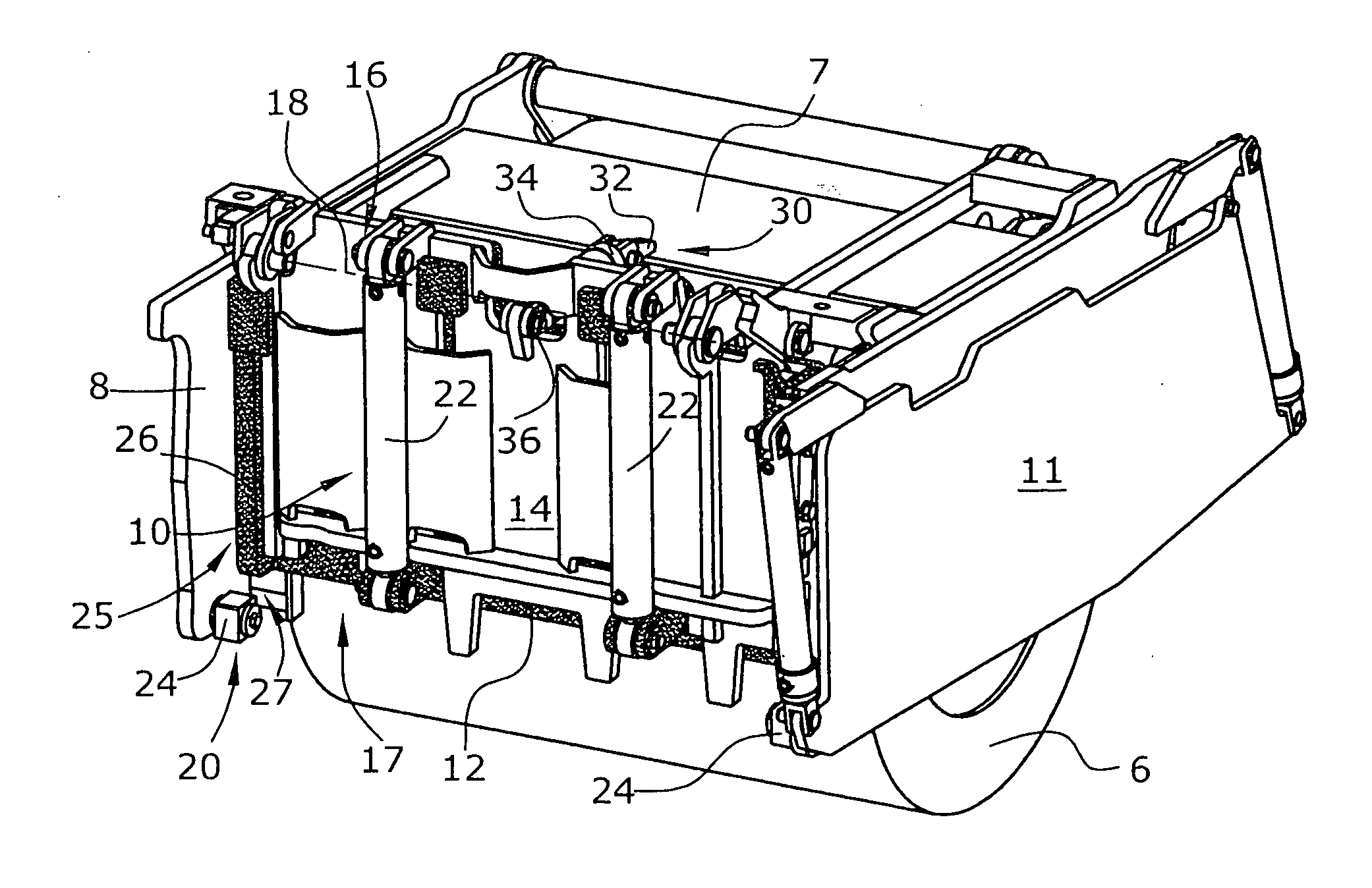
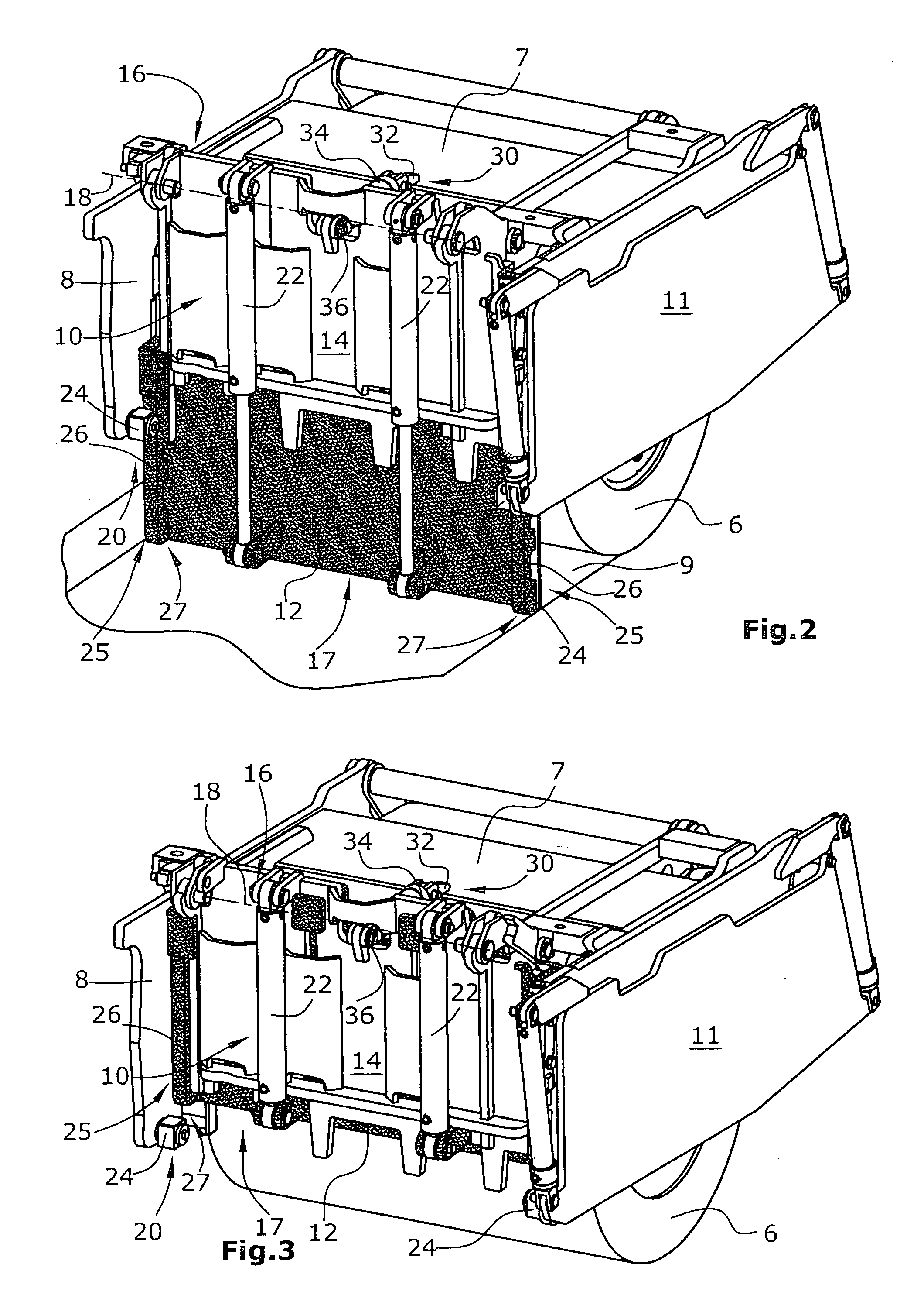
[0048]The milling drum 6 is surrounded by a drum casing 7 attached to the machine frame 4, the said drum casing 7 being provided with, at the rear end when seen in the direction of travel, a scraper device with a two-part scraper blade 10. The lower part 12 of the scraper blade 10 can glide over the ground surface 9 milled off by the milling drum 6 during operation, with the lower part 12 of the scraper blade 10 being adjustable in height relative to the milling drum 6.

[0049]It goes without saying that the scraper device with a two-part scraper blade 10 is also suitable for use in other road milling machines of different design.

[0050]In addition to the side walls 8, a height-adjustable side plate 11 may additionally be provided as edge ...


PUM

PropertyMeasurementUnit
swivelling angleaaaaaaaaaa
heightaaaaaaaaaa
horizontal distanceaaaaaaaaaa

Abstract

A scraper device for a milling drum mounted in a construction machine at a machine frame between lateral walls with a milling drum axis, with a two-part scraper blade arranged in a height-adjustable fashion behind the milling drum when seen in the direction of travel, the lower part of which can glide over the ground surface milled off by the milling drum, where the lower part of the scraper blade is adjustable in height when in operating position, it is provided that the upper part of the scraper blade is attached, at the upper end, to swivel about a swivelling axis parallel to the axis of the milling drum, that the scraper blade, when in operating position, is engaged with lateral retaining devices at the lateral walls, which retain the scraper blade in a position running essentially orthogonally to the ground surface, that a swivelling device is capable of swivelling the scraper blade about the swivelling axis when the scraper blade is disengaged from the lateral retaining devices, and that the swivelling device is provided, at the upper end of the upper part of the scraper blade, with an operating device articulated between a permanently installed part of the construction machine and the upper part of the scraper blade.

Description

BACKGROUND OF THE INVENTION[0001]The invention relates to a scraper device, as well as a construction machine.[0002]A scraper device for a milling drum mounted in a construction machine at a machine frame in lateral walls, with a scraper blade arranged in a height-adjustable fashion behind the milling drum when seen in the direction of travel, is known from DE 10 2005 058 102. With this scraper device, the lower part of the scraper blade can glide over the ground surface milled off by the milling drum, with the scraper blade being guided in a height-adjustable fashion relative to the milling drum.[0003]From DE 35 28 038, it is known in a scraper device with a single-part scraper blade to use a scraper blade capable of swivelling. A laterally arranged retaining groove causes the lifting movement of the scraper blade to turn into a swivelling movement towards the end of the path of a lifting cylinder.[0004]It is also known from U.S. Pat. No. 5,505,598 and U.S. Pat. No. 5,474,397 to us...

Claims


Application Information

Patent Timeline
Patent Type & Authority Applications(United States)
IPC IPC(8): B08B7/00
CPCE01C23/088E01C23/127E02F3/783E02F3/7645
Inventor KOTTING, HEINZLEY, HERBERTHAHN, GUNTER
Owner WIRTGEN AMERICA
Why Eureka
Try Eureka