

Method of making a bumper structure of a motor vehicle, and bumper structure
- Summary
- Abstract
- Description
- Claims
- Application Information
AI Technical Summary
Benefits of technology
Problems solved by technology
Method used
Image

Examples
first embodiment
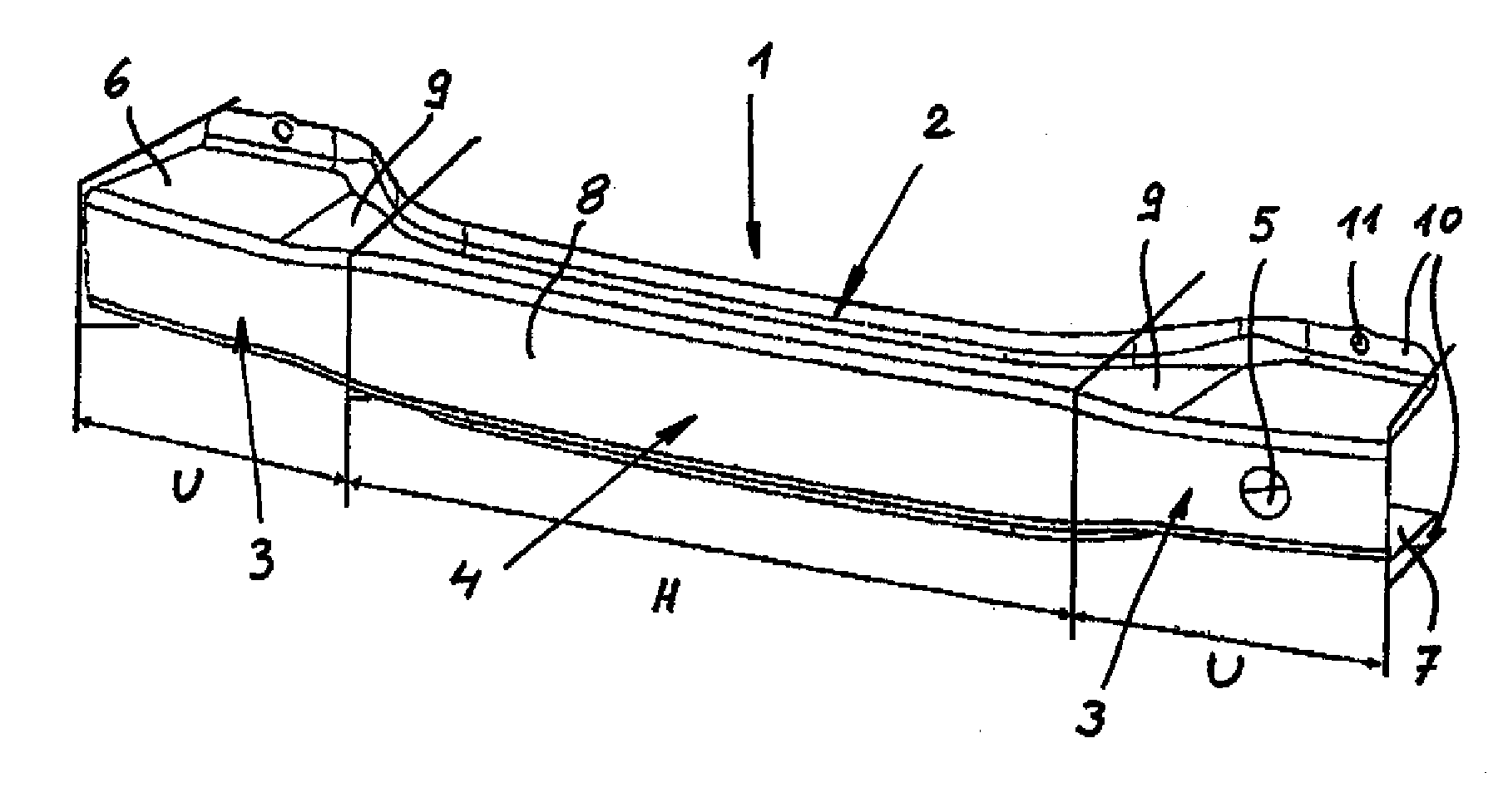
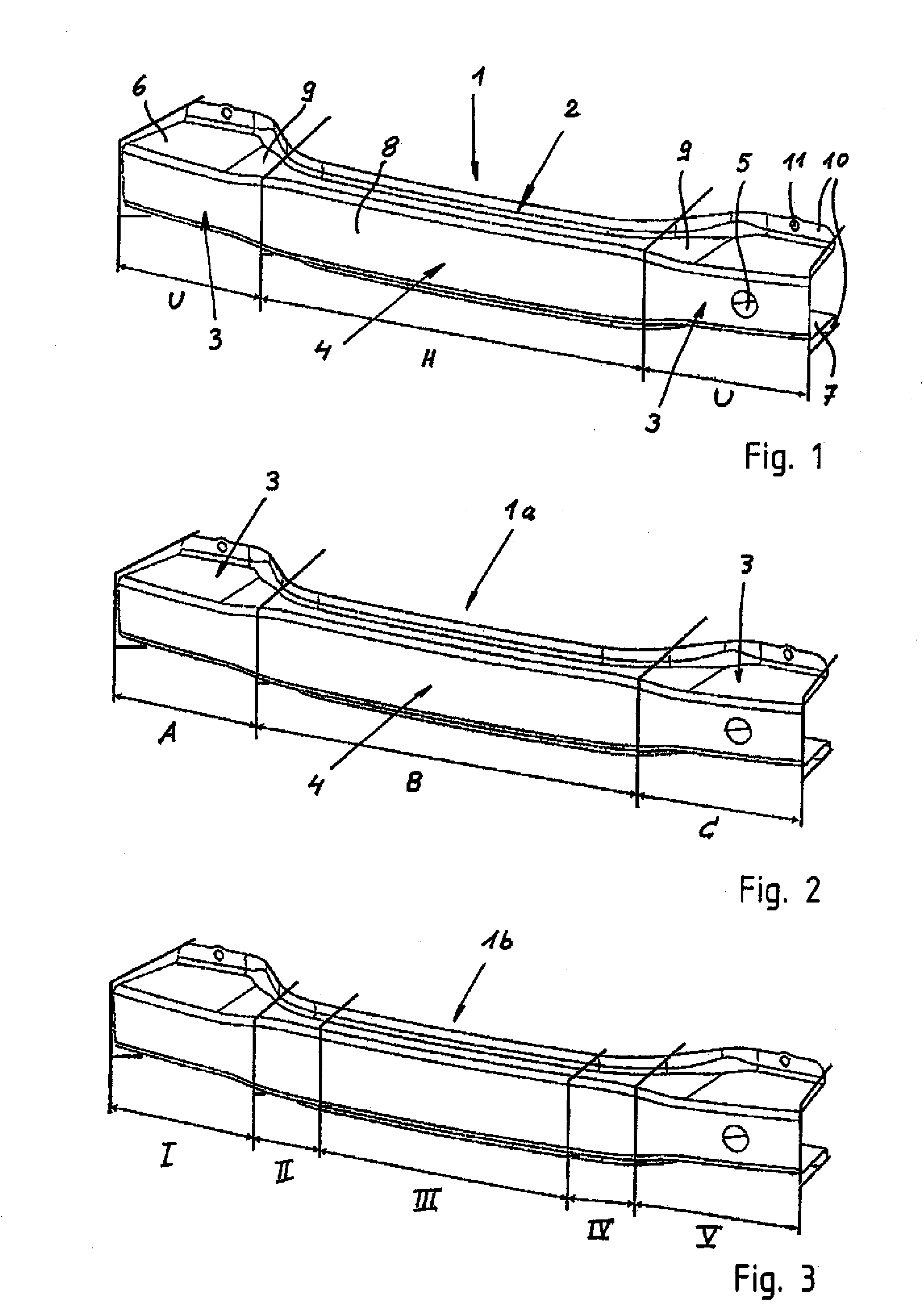
[0031]Turning now to the drawing, and in particular to FIG. 1, there is shown a perspective view of a bumper structure according to the present invention, generally designated by reference numeral 1 for an unillustrated motor vehicle. The bumper structure 1 is made from a blank of quenched and tempered steel and formed to have a profiled U-shaped cross section. The bumper structure 1 includes two functional components, namely a bumper beam 2 and crash boxes formed in one piece with the bumper beam 2. The crash boxes are hereby formed by terminal attachment parts 3 by the bumper beam 2 is mounted to the side rails of the motor vehicle. The area between the attachment parts 3 is referred to as middle part 4.
[0032]The U-shaped bumper beam 2 points with its open side in the direction of the side rails which are not shown in detail. As a result, the bumper beam 2 has a closed front side, except for an opening 5 for feedthrough of a tow lug in the attachment part 3 to the right in the dra...
second embodiment
[0035]Referring now to FIG. 2, there is shown a bumper structure according to the present invention, generally designated by reference sign 1a. Parts corresponding with those in FIG. 1 are denoted by identical reference numerals and not explained again. The description below will center on the differences between the embodiments. In this embodiment, the bumper structure 1a is made of a blank which has areas of different wall thicknesses and / or different material grade. The blank used for making the bumper structure 1a is a tailored welded blank which is configured such that a steel A is used for making the area of the attachment part 3 to the left of the drawing plane, whereas the middle part 4 is made of a steel B and the attachment part 3 to the right of the drawing plane is made of a steel C. The areas across which the individual steels extend are characterized by the reference signs A, B, C. The steels A, B, C stand for different material grades as well as for different wall thi...
third embodiment
[0036]FIG. 3 shows a bumper structure according to the present invention, generally designated by reference sign 1b and made from a tailored rolled blank. The bumper structure 1b differs from the bumper structure 1a by differences in wall thickness which are less sudden. Moreover, the tailored roll blank is made of a single material having thickness areas designated by Roman numerals I, II, III, IV, V. It is conceivable to provide the areas I and V of same wall thickness. Of course, deviations between all wall thickness areas as well as additional heat treatments are possible to best suit the bumper structure 1b to the demands in the event of a crash.
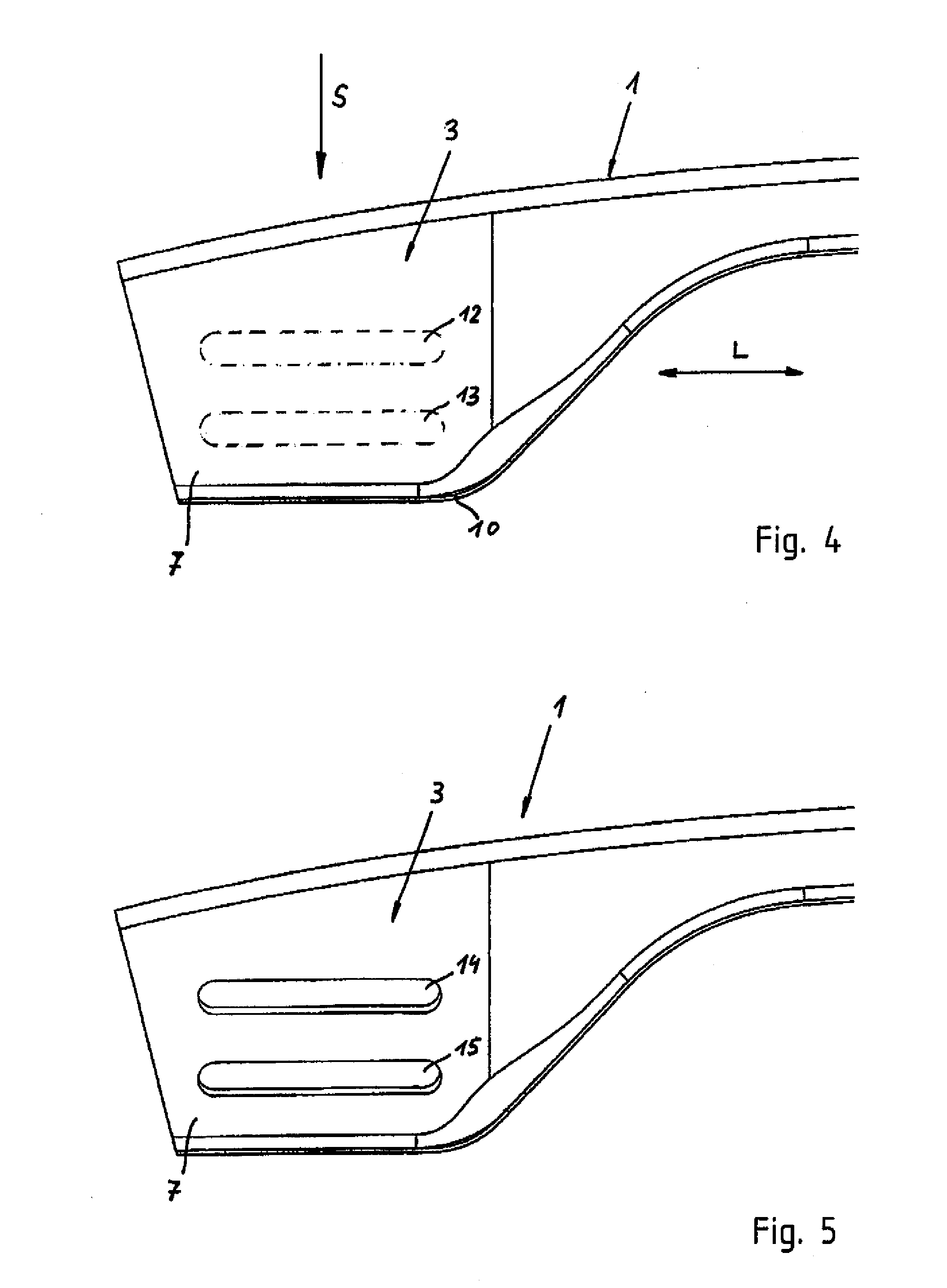
[0037]FIG. 4 shows a plan view of a detail of the bumper structure 1, depicting in particular an attachment part 3 which is hardened except for the regions 12, 13 shown in broken line. The regions 12, 13 have been disregarded during the hardening process or underwent a heat treatment to reduce the strength again. The unhardened or heate...
PUM
| Property | Measurement | Unit |
|---|---|---|
| Length | aaaaa | aaaaa |
| Thickness | aaaaa | aaaaa |
| Area | aaaaa | aaaaa |
Abstract
Description
Claims
Application Information