Working Abnormality Detecting Device and Working Abnormality Detecting Method for Machine Tool

a technology of working abnormality and detecting device, which is applied in the direction of process and machine control, program control, instruments, etc., can solve the problems of deteriorating processing efficiency, reducing the efficiency of cutting work, and attempting to realize automation and highly efficient operation. , to achieve the effect of reducing the cost of products, improving processing efficiency, and improving cutting work efficiency

Inactive Publication Date: 2014-05-08
HITACHI LTD
View PDF10 Cites 27 Cited by
  • Summary
  • Abstract
  • Description
  • Claims
  • Application Information

AI Technical Summary

Benefits of technology

[0014]According to the present invention, it becomes possible to determine a threshold value for detecting abnormality of the predicted value of cutting force to be compared based on the measurement value of the cutting quantity, so that it becomes possible to detect abnormality in machining a curved surface, to improve the efficiency of the cutting work and to cut down costs of the products.
[0015]Even further according to the present invention, the working abnormality detecting device of the numerically controlled machine tool has the measurement means of the machine tool built into the spindle of the machining device, such as a force sensor disposed between the table of the machining device and the cut target material, so that the configuration can be realized inexpensively compared to forming a dedicated numerically controlled machine tool, and can be easily realized in a general-purpose numerically controlled machine tool.

Problems solved by technology

Recently, in order to enhance the product performance, high-intensity, difficult-to-cut materials such as Ni-based alloy and super-hard cast steel material are often adopted in components being the target of the cutting work, so that the cutting conditions must be set with a deteriorated processing efficiency, causing a drawback in the attempt to realize automation and highly efficient operation.
Furthermore, the processing shapes have become complex, such as with a three-dimensional curved surface, so that more and more processing is performed using a multiaxial machine tool such as a five-axis machining center, and the improvement of processing efficiency to overcome the above-mentioned drawback has become a problem.
In processing such materials into desirred shapes, depending on the cutting quantity or the rotation speed of the rotation shaft, the force applied on the cutting blade increases when the cutting quantity or the tool rotation speed is increased, so that processing problems caused by vibration (chatter) of the tool or the wear and damage of the cutting blade occur easily.
When such processing problem occurs, the surface roughness of the processed section may be deteriorated or damaged, and material must be discarded, so that expensive high-intensity material and tools are lost and disposal costs occur, causing increase of manufacturing costs.

Method used


Image

  • Working Abnormality Detecting Device and Working Abnormality Detecting Method for Machine Tool
  • Working Abnormality Detecting Device and Working Abnormality Detecting Method for Machine Tool
  • Working Abnormality Detecting Device and Working Abnormality Detecting Method for Machine Tool

Examples


embodiment 1

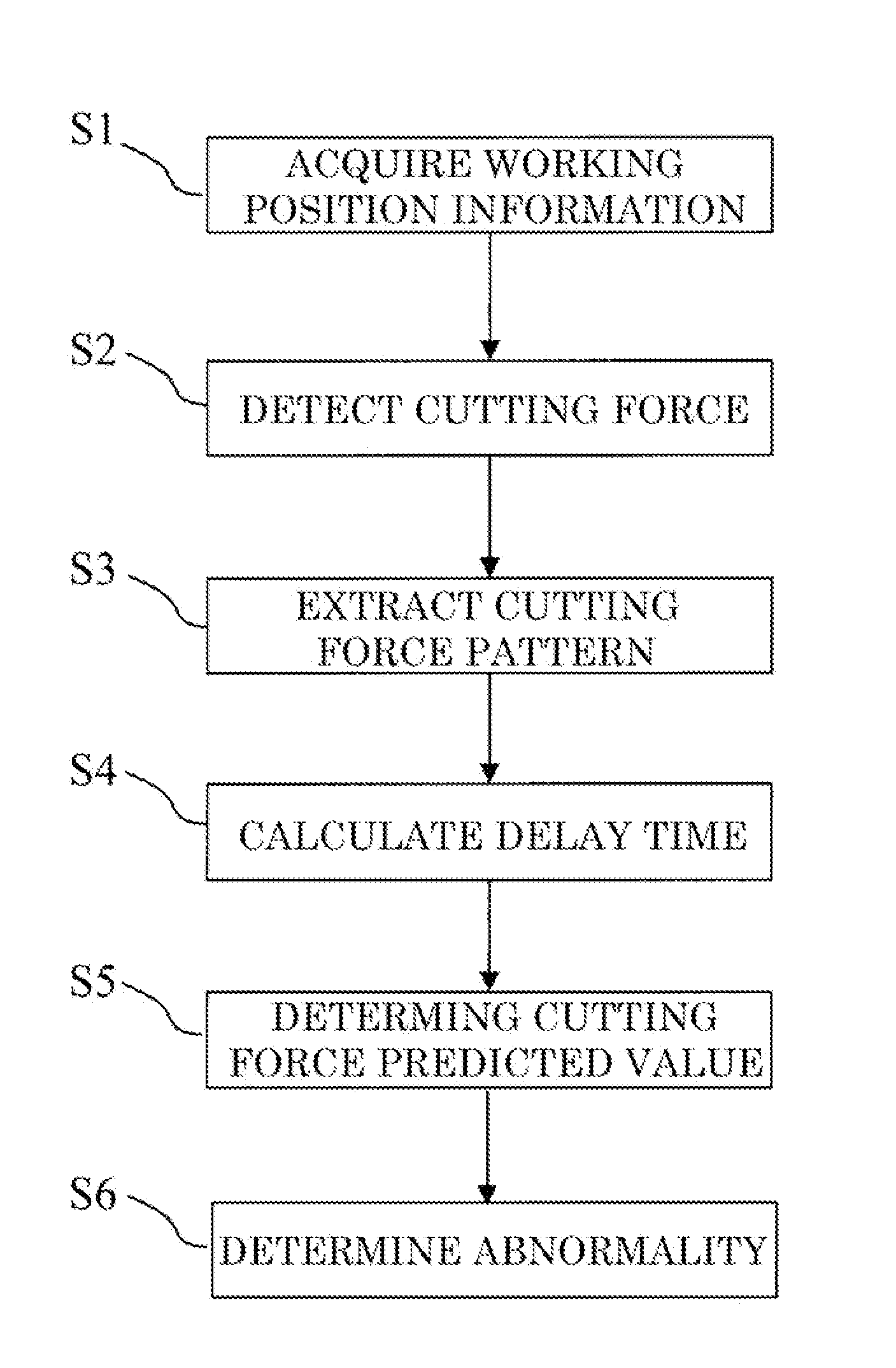
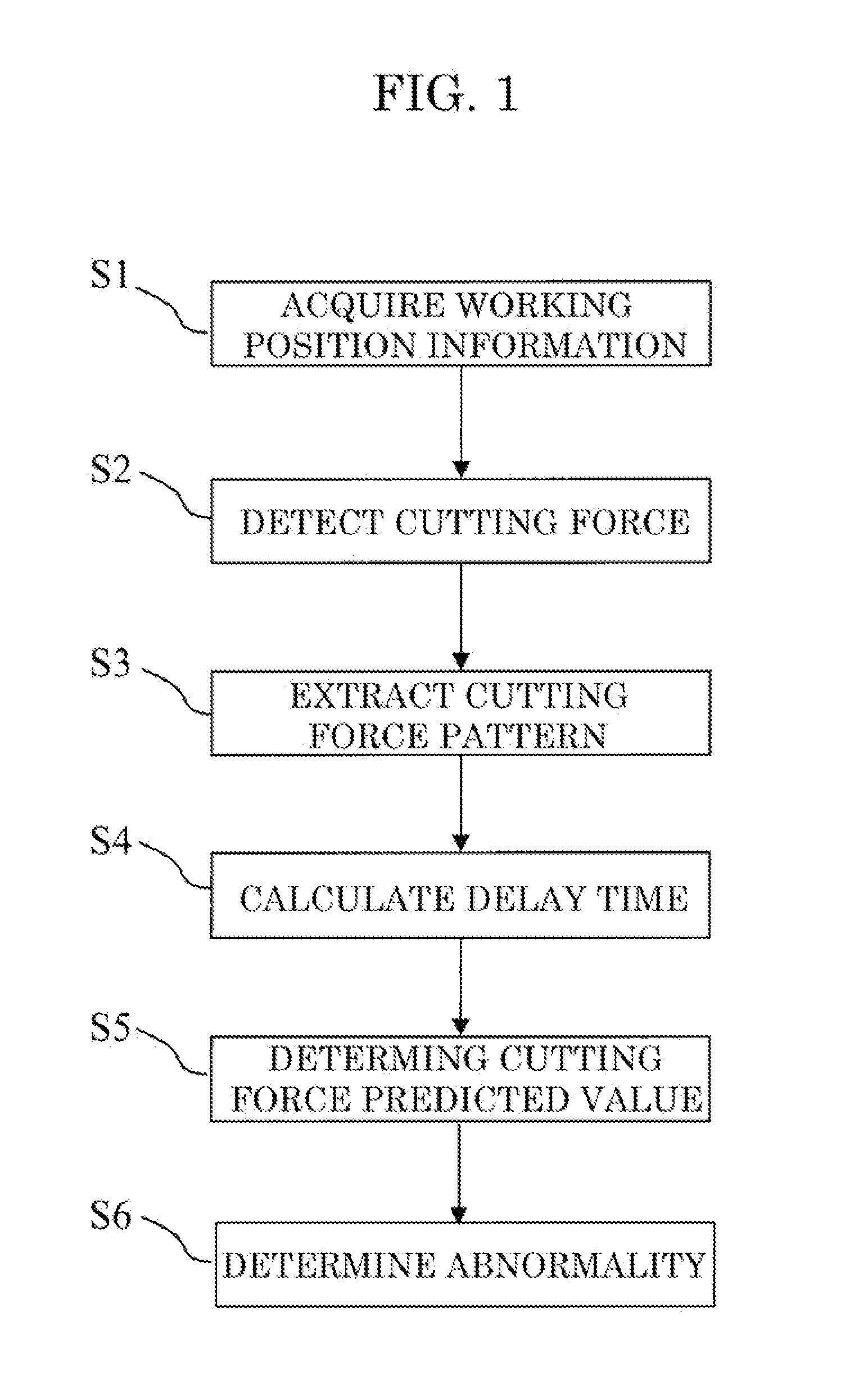
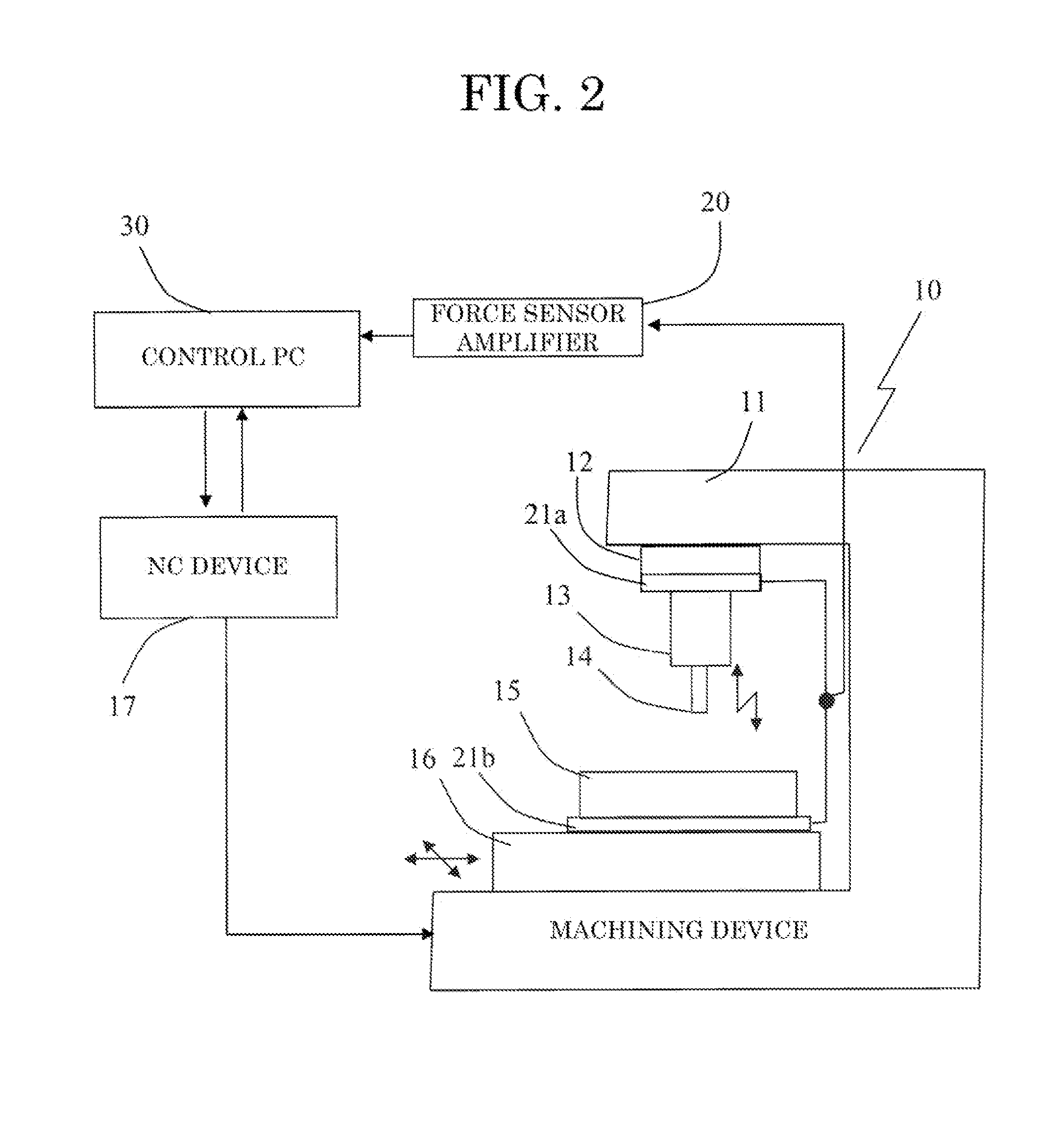
[0028]The first embodiment of the present invention will be described with reference to FIGS. 1 through 9. FIG. 2 shows an outline of the components constituting a device of a machining control system of a machine tool according to the preferred embodiment of the present invention. The present embodiment takes a machining device performing triaxial control as an example, but the number of controlled axes or the configuration of the device is not limited to the illustrated example. The present machining control system is applied to a machining device 10 which is a common triaxially-controlled machine tool, composed of a chassis 11 of the machining device 10, a working tool 14, a spindle 13 holding and rotating the working tool 14, a spindle stage 12 for moving the spindle 13 in a Z-axis direction (vertical direction), a cut target material 15, a table 16 for holding and moving the cut target material in the direction of X-Y axes (horizontal direction), an NC device 17 for controlling...

embodiment 2

[0045]Now, a system configuration of a working abnormality detecting device as a second embodiment of the present invention will be described with reference to FIG. 10. FIG. 10 is a view showing the relationship between components for describing a preferred embodiment of the working abnormality detecting device. The working abnormality detecting device according to the present invention is composed of a cutting force measurement unit 101, a coordinate value acquisition unit 102, a cutting force variation comparison operation unit 103, a delay time calculation unit 104, a cutting force comparison unit 105, an abnormality determination unit 106, a cutting position—work condition storage unit 107, a calculated cutting force storage unit 108, a threshold cutting force storage unit 109, and an abnormality detection threshold value calculation unit 110.

[0046]The cutting force measurement unit 101 is a means for measuring the cutting load applied on the tool as cutting force using a piezoe...


PUM

PropertyMeasurementUnit
cutting forceaaaaaaaaaa
threshold cutting forceaaaaaaaaaa
shapesaaaaaaaaaa

Abstract

Provided are a device and a method which determine a threshold value for detecting abnormality in a working path in which the cutting condition changes momentarily to thereby enable abnormality determination. Cutting force that becomes an abnormality determination value and threshold value information are previously calculated by cutting simulation, and a threshold value with which a comparison is to be made is determined from the position coordinates of a working machine which have been acquired during cutting and the measurement result of cutting force to thereby enable abnormality determination.

Description

TECHNICAL FIELD [0001]The present invention relates to a control device and control method for detecting working abnormalities such as tool wear and chatter vibration that occur during processing, and suppressing the working abnormality caused by work damage due to excessive wear or chatter vibration, in a machine tool subjected to numerical control, and especially in a machine tool subjected to numerical control used for milling and cutting operations.[0002]Further, the preset invention relates to a working abnormality detecting device and working abnormality detecting method in a machine tool subjected to numerical control, wherein a cutting force as abnormality determination value (model) based on a cutting simulation corresponding to cutting conditions and threshold value information are calculated in advance, and a position coordinate of a cutting tool of the machine tool acquired during actual cutting work and a measurement result of the actual cutting force are acquired to de...

Claims


Application Information

Patent Timeline
Patent Type & Authority Applications(United States)
IPC IPC(8): G01N19/08
CPCG01N19/08B23Q17/0961G05B19/406G05B2219/50197
Inventor YOSHIKAWA, TAKEHISAONOZUKA, HIDEAKINAKASU, NOBUAKI
Owner HITACHI LTD
Why Eureka
Try Eureka