Locating device of laser cutting platform

A positioning device and laser cutting technology, applied in laser welding equipment, welding equipment, metal processing equipment and other directions, can solve the problems of low accuracy, slow positioning, affecting cutting efficiency, etc., to improve positioning accuracy, convenient adjustment, and improve cutting The effect of work efficiency

Inactive Publication Date: 2014-02-12
无锡洲翔成套焊接设备有限公司
View PDF7 Cites 2 Cited by
  • Summary
  • Abstract
  • Description
  • Claims
  • Application Information

AI Technical Summary

Problems solved by technology

The positioning of the existing cutting platforms all rely on manual operation, which is slow in positioning and low in precision, which affects the efficiency of cutting work

Method used


Image

  • Locating device of laser cutting platform

Examples


Embodiment Construction

[0011] The present invention will be further described below in conjunction with specific drawings and embodiments.

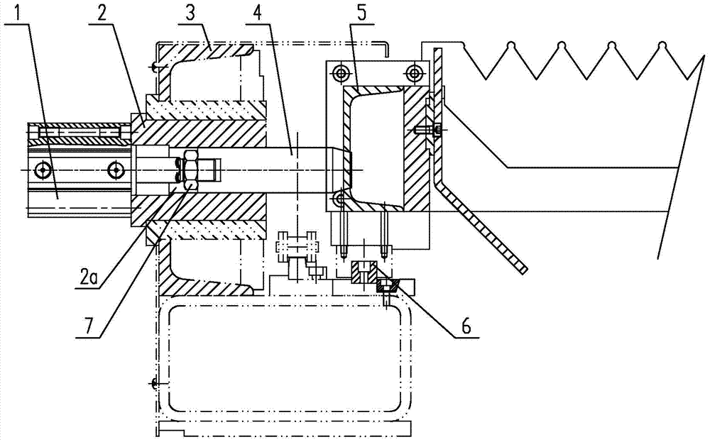
[0012] As shown in the figure: the laser cutting platform positioning device in the embodiment is mainly composed of a cylinder 1, a fixed seat 2 and a positioning shaft 4, the fixed seat 2 is installed on the side of the frame 3, and the cylinder 1 is installed outside the positioning seat On the side, the center of the fixed seat 2 is provided with a through hole 2a, the positioning shaft 4 is placed in the through hole 2a and can slide axially, the rear end of the positioning shaft 4 is connected with the piston rod end of the cylinder 1, and the positioning The front end of the shaft 4 is used to insert into the positioning hole on the cutting platform 5 to realize the positioning of the cutting platform 5 .

[0013] Such as figure 1 As shown, in the embodiment of the present invention, the front end of the positioning shaft 4 is in the shape of a truncat...


PUM


Abstract

The invention relates to a locating device of a laser cutting platform. The locating device is characterized by comprising an air cylinder, a fixing base and a locating shaft. The fixing base is installed on the side of a rack, the air cylinder is installed on the outer side face of a locating base, a through hole is formed in the center of the fixing base, the locating shaft is arranged in the through hole and can axially slide, the rear end of the locating shaft is connected with the end of a piston rod of the air cylinder, the front end of the locating shaft is inserted into a locating hole in the cutting platform, and then the cutting platform is located. The locating device is simple and compact in structure, attractive in appearance, convenient to install, maintain and adjust, and accurate and reliable in locating, time and labor are saved, locating accuracy of the cutting platform can be improved, and cutting work efficiency is improved.

Description

technical field [0001] The invention relates to a positioning device for a laser cutting platform, which belongs to the technical field of laser cutting equipment. Background technique [0002] In the laser cutting machine, the cutting platform plays the role of placing the cutting plate. In order to improve cutting efficiency, large-scale laser cutting machines use two cutting platforms for exchange cutting, that is, one cutting platform cuts in the working area, and the other cutting platform removes the cut plate outside the cutting area, and then reinstalls it. Go to the plate waiting to be cut, and wait for the platform to be exchanged before cutting. Since the cutting platform needs to move, the cutting platform must be moved to an accurate position to perform cutting, so the cutting platform needs to be equipped with a positioning device. The positioning of the existing cutting platform all relies on manual operation, the positioning is slow and the precision is low...

Claims


Application Information

Patent Timeline
Patent Type & Authority Applications(China)
IPC IPC(8): B23K26/38B23K26/70
CPCB23K26/38B23K26/702
Inventor 徐旦徐惠忠师恩托
Owner 无锡洲翔成套焊接设备有限公司
Why Eureka
Try Eureka