Apparatus for Mounting an Article Astride Fixed and Movable Body Components

Active Publication Date: 2009-02-19
GM GLOBAL TECH OPERATIONS LLC
View PDF4 Cites 0 Cited by
  • Summary
  • Abstract
  • Description
  • Claims
  • Application Information

AI Technical Summary

Benefits of technology

[0007]The present invention is a mounting apparatus for an article in which the article is mounted astride both a fixed body component and a movable body component, as for example astride a front fender and its adjoining door. The article is disposed so as to bridge across the cut-line therebetween, wherein the article is automatically pivoted with respect to the fixed body component responsive to movement of the movable body component such that the pivoting of the article ensures that as the movable body component moves with respect to the fixed body component, interference by the article with respect to the movement of the movable body component is prevented and contact between the article and the movable body component is avoided.
[0009]In operation, when the movable body component is moved from its rest position to another position relative to the fixed body component, as for example when a front door is rotated open on its hinge from its closed position, the linkage apparatus automatically causes the article to pivot generally transversely out of the seated position, wherein the pivoting movement is generally in unison with the movement of the movable body component such that as the article pivots, a portion thereof into the opening of the fixed body component and another portion thereof away from the movable body component, the article avoids contact with the movable body component and keeps out of interference with the movement of the movable body component. As the movable body component is returned to its rest position (i.e., the door is rotated closed), the linkage apparatus returns the article to its original seated position at a rate such that contact between the article and the movable body component is always avoided whenever the movable body component is at other than its rest position.

Problems solved by technology

Such an article mounting has heretofor been an impossibility because if a rigid article was to somehow be mounted astride both fixed and movable body components across the cut-line therebetween, such a disposed article would damagingly contact the movable body component and interfere with the relative movement of the movable body component with respect to the fixed body component.

Method used


Image

  • Apparatus for Mounting an Article Astride Fixed and Movable Body Components
  • Apparatus for Mounting an Article Astride Fixed and Movable Body Components
  • Apparatus for Mounting an Article Astride Fixed and Movable Body Components

Examples


Embodiment Construction

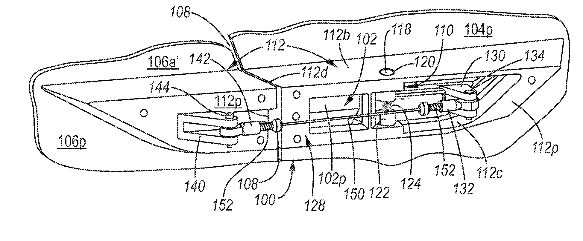
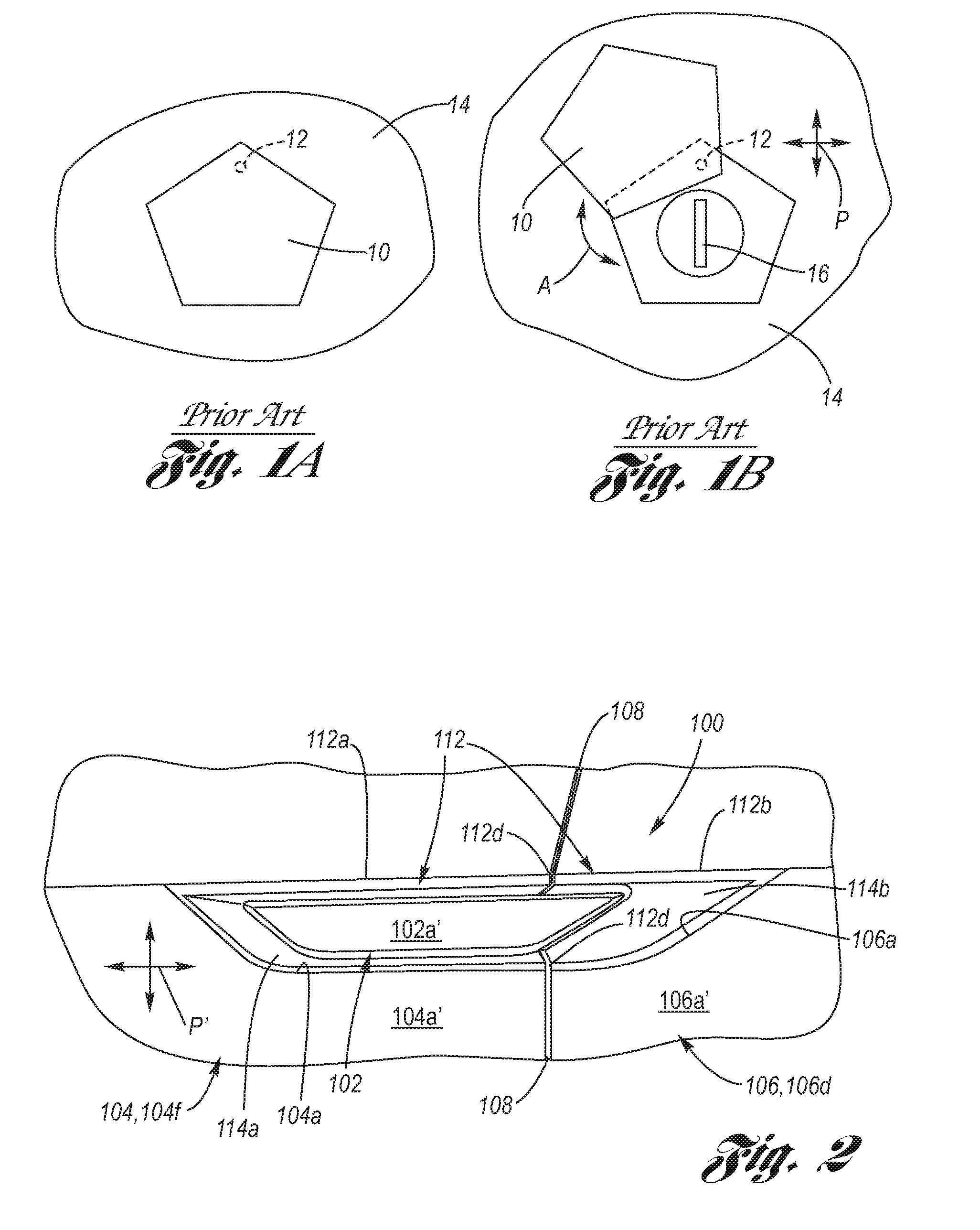
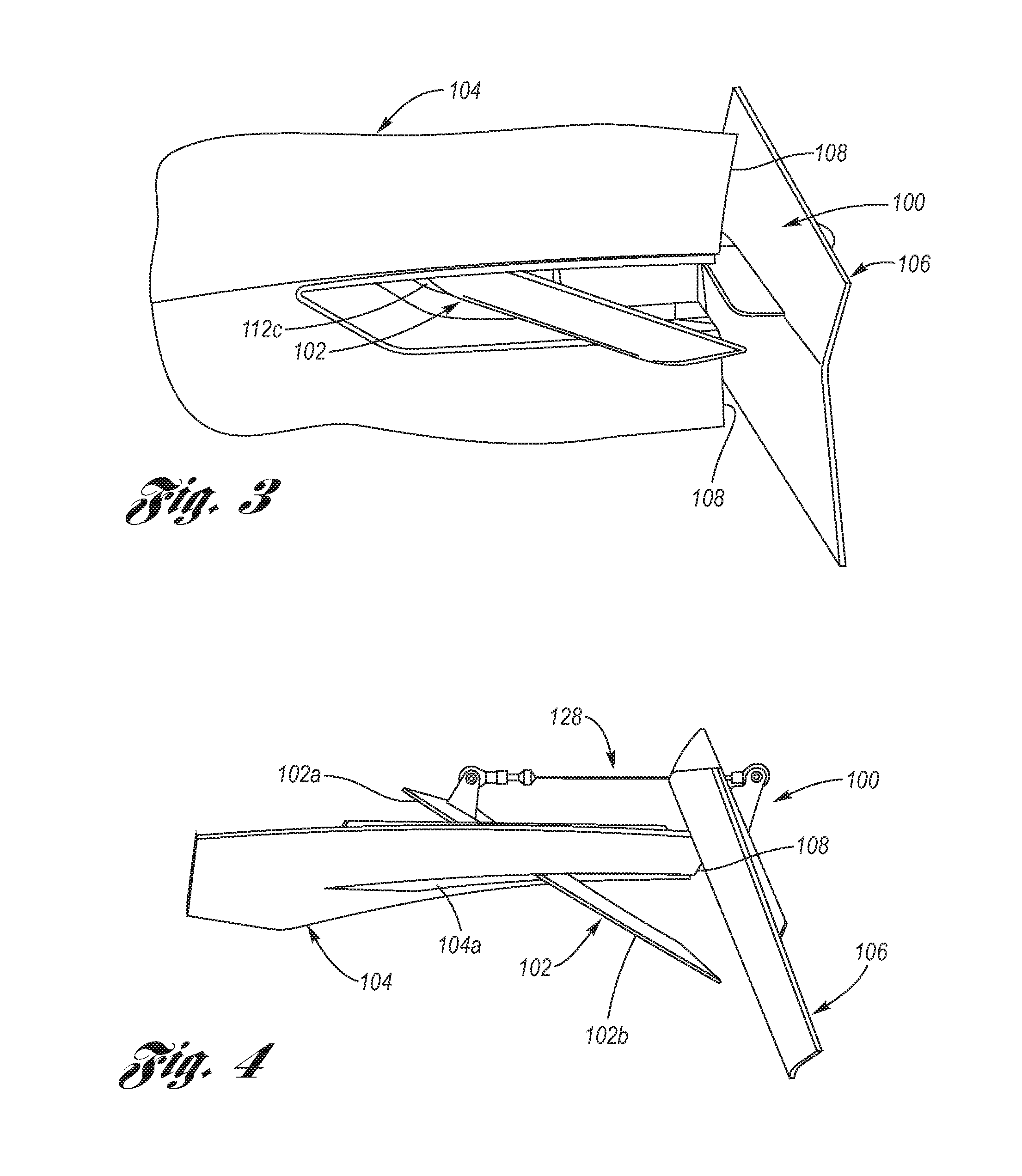
[0019]Referring now to the Drawing, FIGS. 2 through 7 depict an example of an article mounting apparatus 100 according to the present invention.

[0020]As shown at FIG. 2, an article 102 is disposed astride a fixed body component 104 (as for non-limiting example, a front fender 104f of a motor vehicle) and a movable body component 106 (as for non-limiting example, a door 106d of the motor vehicle, wherein the door has its hinge adjacent, and / or connected with, the front fender), wherein a cut-line 108 is present between the fixed and movable body components, and wherein the article bridges the cut-line. The article 102 may be, for non-limiting example, a badge, emblem, vent, molding, decoration, etc. The article 102 is preferably a single piece and is preferably rigid, but in any case the article bridges (in other words spans, extends across, straddles) the cut-line 108 without, itself, thereat having a cut-line formed therein.

[0021]The article 102 is pivotally connected by a pivot 11...


PUM


Abstract

A mounting apparatus for an article astride fixed and movable body components in bridging relation to the cut-line therebetween. The article is automatically pivoted with respect to the fixed body component in concert with movement of the movable body component, whereby the pivoting of the article ensures that the movement of the movable body component with respect to the fixed body component avoids contact and interference with the article. For example, an article astride a fender and a door of a motor vehicle, the article transversely pivots out of the way of the door whenever the door is opened.

Description

TECHNICAL FIELD[0001]The present invention relates to articles used in the styling of motor vehicles, as for example vents, badges, emblems, covers, moldings, etc. Still more particularly, the present invention relates to a pivotally mounted article astride movable and fixed body components, as for example in straddling relation across the cut-line between a fender and a door.BACKGROUND OF THE INVENTION[0002]Motor vehicle design includes a range of ornamentation, badges, emblems, vents, moldings and other articles which are integrated with body components of the vehicle.[0003]Articles in the form of badges, emblems, and the like are used in the automotive arts to provide identification (i.e., model and make monikers) and / or ornamentation, which are placed on the anterior (externally visible side) of body components of the vehicle. It is known in the art to provide badges and emblems with not only a fixed attachment, but a pivoting attachment, wherein the pivoting occurs parallel to ...

Claims


Application Information

Patent Timeline
IPC IPC(8): B62D25/00
CPCB62D25/00
Inventor THOMAS, BOBBROWN, JACK E.KRIEG, ROBIN
Owner GM GLOBAL TECH OPERATIONS LLC
Why Eureka
Try Eureka