Current steering dac

a current steering and dac technology, applied in the direction of digital-analog convertors, power saving provisions, instruments, etc., can solve the problems of power consumption increase and power consumption reduction, and achieve the effect of reducing unnecessary power consumption and reducing resolution without degrading

Active Publication Date: 2009-02-19
SOCIONEXT INC
View PDF5 Cites 35 Cited by
  • Summary
  • Abstract
  • Description
  • Claims
  • Application Information

AI Technical Summary

Benefits of technology

[0028]As has been described above, a multi-channel current steering DAC of the invention is capable of adjusting a full-scale current of each channel without degrading the resolution. Accordingly, unnecessary power consumption can be effectively reduced.
[0029]The current steering DAC of the invention is capable of variably adjusting a full-scale current only by a current signal of an internal control circuit.

Problems solved by technology

Moreover, since an LSI (Large Scale Integrated circuit) has multiple functions, power consumption has been increasing and reduction in power consumption has been a big challenge.

Method used


Image

  • Current steering dac
  • Current steering dac
  • Current steering dac

Examples


first embodiment

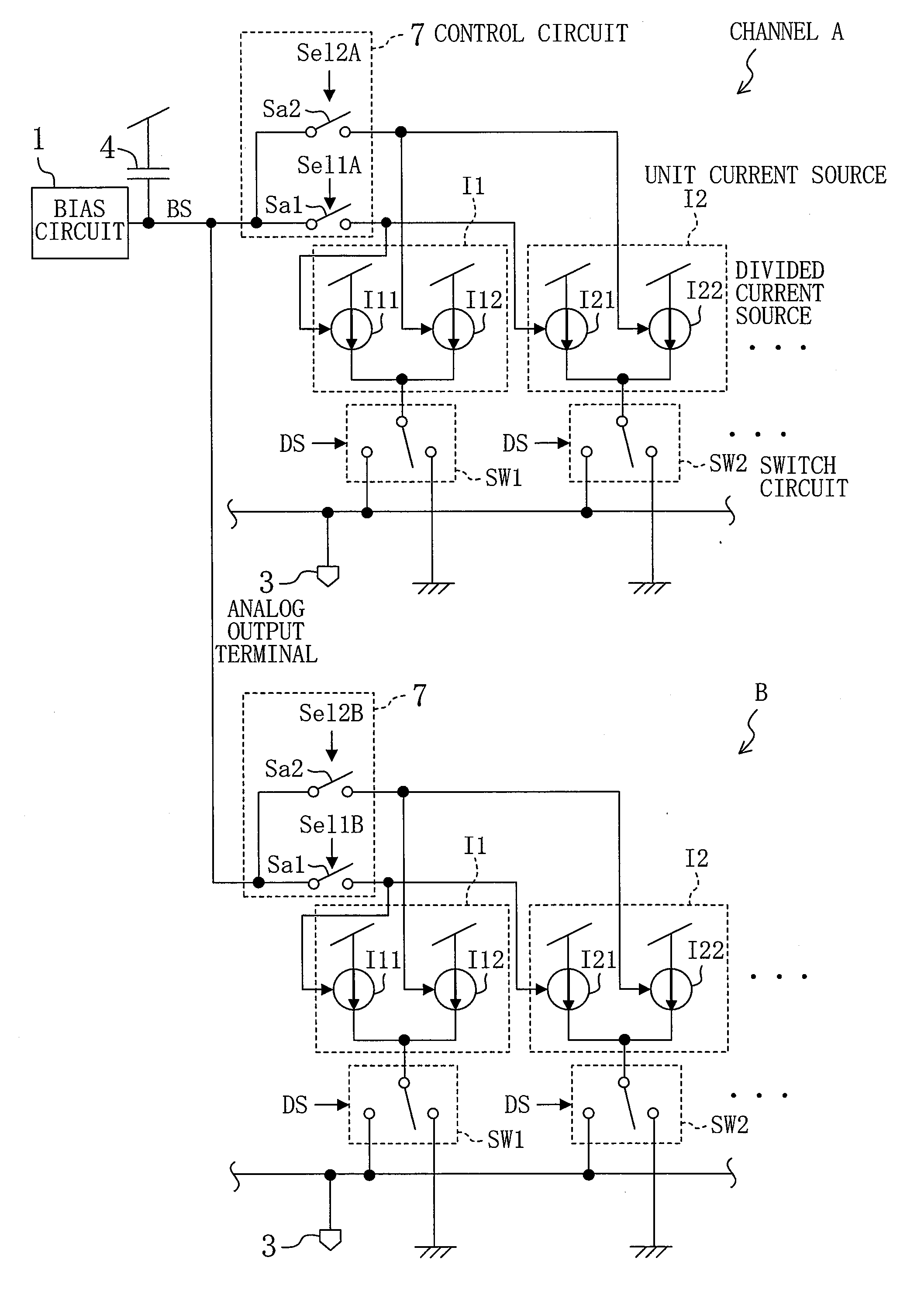
[0062]FIG. 1 shows the structure of a current steering DAC according to a first embodiment of the invention.

[0063]The current steering DAC of FIG. 1 is a 2-channel current steering DAC. Since two channels A, B have the same structure, only the channel A will be described below.

[0064]In the channel A, 1 indicates a bias circuit that is shared with the channel B, and DS indicates a digital input signal. 11, I2, . . . indicate unit current sources. The number of unit current sources correspond to the number of bits of the digital input signal DS. In the case of a thermometer-type current steering DAC, each channel includes 256 unit current sources in the case of an 8-bit digital input signal DS and includes 1,024 unit current sources in the case of a 10-bit digital input signal DS. In the case of a binary-type current steering DAC, each channel includes eight weighted unit current sources in the case of an 8-bit digital input signal DS. Only two unit current sources are shown in FIG. 1...

second embodiment

[0071]Hereinafter, a second embodiment of the invention will be described.

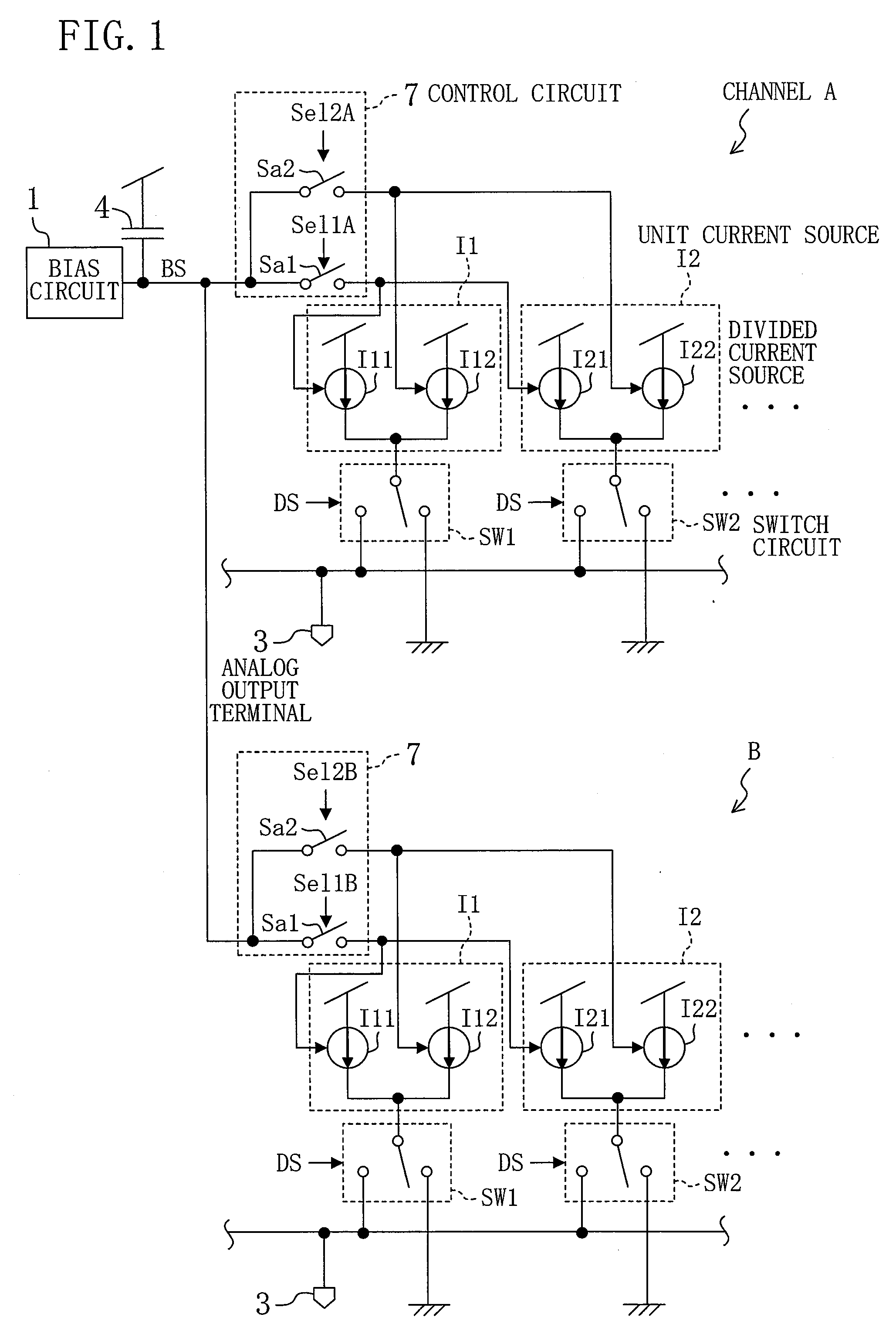
[0072]FIG. 2 shows the structure of a current steering DAC according to the second embodiment of the invention.

[0073]In the current steering DAC of FIG. 2, divided current sources I11, I12, I21, I22, . . . are respectively formed by Pch transistors P11, P12, P21, P22, . . . . The respective sources of the Pch transistors P11, P12, P21, P22, . . . are connected to a power supply vps having a prescribed power supply voltage. The respective drains of two Pch transistors (first and second divided current sources) P11, P12 of the unit current source I1 are connected to a switch circuit SW1, and the respective drains of two Pch transistors (first and second divided current sources) P21, P22 of the unit current source I2 are connected to a switch circuit SW2.

[0074]A bias circuit 1′ outputs a bias voltage signal BS for setting a current value of each unit current source I1, I2, . . . , that is, an on-bias voltage for ...

third embodiment

[0081]FIG. 4 shows the structure of a current steering DAC according to a third embodiment of the invention.

[0082]The current steering DAC of FIG. 4 is a modification of the current steering DAC of FIG. 2.

[0083]More specifically, a bias circuit 1′ supplies an on-bias voltage signal BS to divided current sources I11, I12, . . . formed by Pch transistors. First and second cascode transistors Cd11, Cd12, . . . are formed by Pch transistors. The respective sources of the first and second cascode transistors Cd11, Cd12, . . . are connected in series with the divided current sources I11, I12, . . . , respectively. A corresponding switch circuit SW1, SW2 is connected to the respective drains of the cascode transistors Cd11, Cd12, . . . .

[0084]A selection circuit Sa1′ switches a voltage to be applied to the respective gates of the first cascode transistors Cd11, Cd21, . . . between the on-bias voltage BS and the off-bias voltage v from the bias circuit 1′. A selection circuit Sa2′ switches ...


PUM


Abstract

A multi-channel current steering DAC (Digital-to-Analog Converter), for example, a 2-channel current steering DAC, includes a plurality of current sources I1, I2, . . . corresponding to the number of bits of a digital input signal DS in each of channels A, B. Each of the plurality of current sources I1, I2, . . . is formed by two small-current sources (I11, I12), (I21, I22), . . . . In the case where a full-scale current is limited to a small value in any of the channels, one of the two divided current sources is turned off by switches Sa1, Sa2. Accordingly, a full-scale current of each channel can be adjusted with a common bias circuit without degrading the resolution.

Description

TECHNICAL FIELD[0001]The invention relates to a current steering DAC (Digital-to-Analog Converter). More particularly, the invention relates to measures for reducing unnecessary power consumption.BACKGROUND ART[0002]Dimensional reduction has been ongoing in a semiconductor process. Unlike a digital circuit block, however, such dimensional reduction in a process does not result in reduction in area of an analog circuit block. Moreover, since an LSI (Large Scale Integrated circuit) has multiple functions, power consumption has been increasing and reduction in power consumption has been a big challenge.[0003]Conventionally, a current steering DAC has a plurality of unit current sources corresponding to the number of bits of a digital input signal, and a bias circuit for generating a bias voltage for adjusting current values of the unit current sources to a prescribed value. When a digital input signal is applied to the current steering DAC, the current steering DAC selects currents to ...

Claims


Application Information

Patent Timeline
Patent Type & Authority Applications(United States)
IPC IPC(8): H03M1/12H03M1/00
CPCH03M1/002H03M1/747H03M1/745H03M1/662
Inventor TOKUMARU, MICHIKOIKOMA, HEIJI
Owner SOCIONEXT INC
Why Eureka
Try Eureka