Current steering DAC
a current steering and dac technology, applied in the direction of digital-analog convertors, power saving provisions, instruments, etc., can solve the problems of power consumption reduction and power consumption increase, and achieve the effect of reducing unnecessary power consumption and reducing resolution without degrading
- Summary
- Abstract
- Description
- Claims
- Application Information
AI Technical Summary
Benefits of technology
Problems solved by technology
Method used
Image
Examples
first embodiment
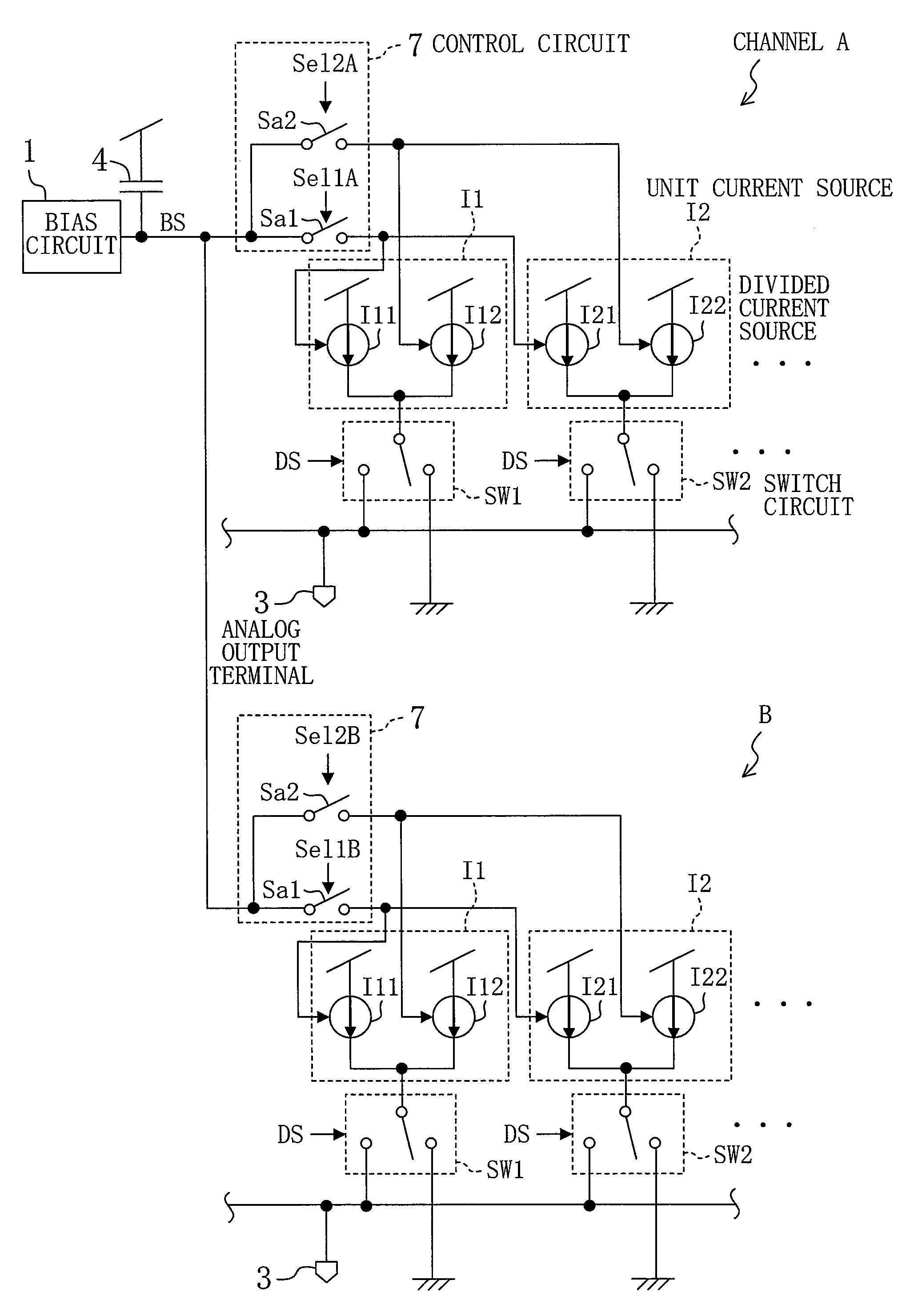
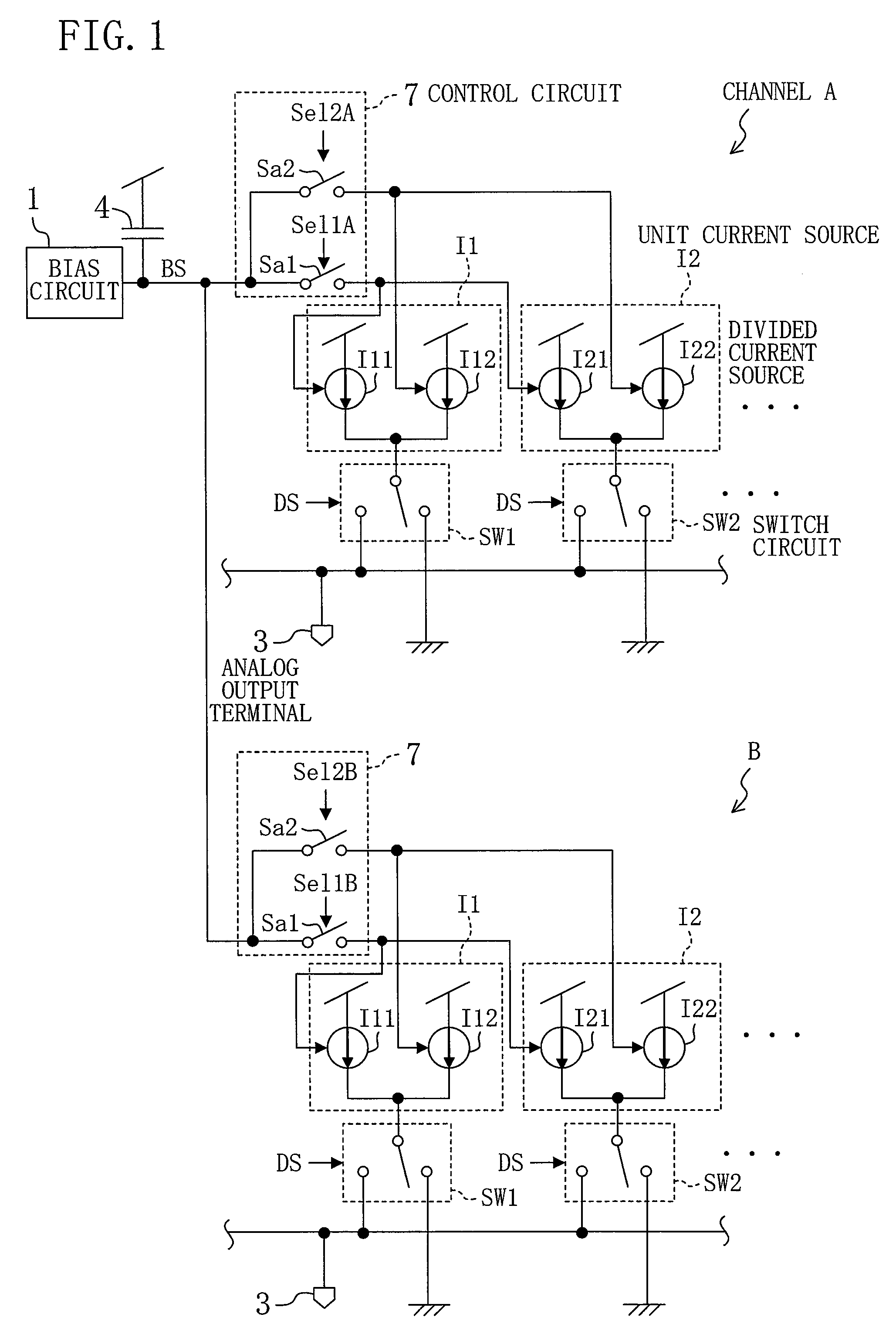
[0042]FIG. 1 shows the structure of a current steering DAC according to a first embodiment of the invention.
[0043]The current steering DAC of FIG. 1 is a 2-channel current steering DAC. Since two channels A, B have the same structure, only the channel A will be described below.
[0044]In the channel A, 1 indicates a bias circuit that is shared with the channel B, and DS indicates a digital input signal. I1, I2, . . . indicate unit current sources. The number of unit current sources correspond to the number of bits of the digital input signal DS. In the case of a thermometer-type current steering DAC, each channel includes 256 unit current sources in the case of an 8-bit digital input signal DS and includes 1,024 unit current sources in the case of a 10-bit digital input signal DS. In the case of a binary-type current steering DAC, each channel includes eight weighted unit current sources in the case of an 8-bit digital input signal DS. Only two unit current sources are shown in FIG. 1...
second embodiment
[0051]Hereinafter, a second embodiment of the invention will be described.
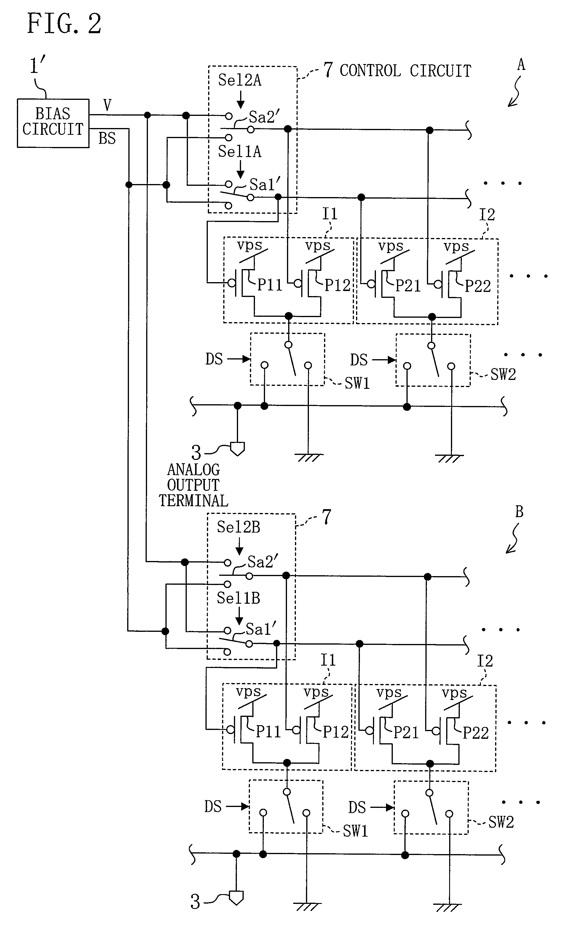
[0052]FIG. 2 shows the structure of a current steering DAC according to the second embodiment of the invention.
[0053]In the current steering DAC of FIG. 2, divided current sources I11, I12, I21, I22, . . . are respectively formed by Pch transistors P11, P12, P21, P22, . . . . The respective sources of the Pch transistors P11, P12, P21, P22, . . . are connected to a power supply vps having a prescribed power supply voltage. The respective drains of two Pch transistors (first and second divided current sources) P11, P12 of the unit current source I1 are connected to a switch circuit SW1, and the respective drains of two Pch transistors (first and second divided current sources) P21, P22 of the unit current source I2 are connected to a switch circuit SW2.
[0054]A bias circuit 1′ outputs a bias voltage signal BS for setting a current value of each unit current source I1, I2, . . . , that is, an on-bias voltage for ...
third embodiment
[0061]FIG. 4 shows the structure of a current steering DAC according to a third embodiment of the invention.
[0062]The current steering DAC of FIG. 4 is a modification of the current steering DAC of FIG. 2.
[0063]More specifically, a bias circuit 1′ supplies an on-bias voltage signal BS to divided current sources I11, I12, . . . formed by Pch transistors. First and second cascode transistors Cd11, Cd12, . . . are formed by Pch transistors. The respective sources of the first and second cascode transistors Cd11, Cd12, . . . are connected in series with the divided current sources I11, I12, . . . , respectively. A corresponding switch circuit SW1, SW2 is connected to the respective drains of the cascode transistors Cd11, Cd12, . . . .
[0064]A selection circuit Sa1′ switches a voltage to be applied to the respective gates of the first cascode transistors Cd11, Cd21, . . . between the on-bias voltage BS and the off-bias voltage v from the bias circuit 1′. A selection circuit Sa2′ switches ...
PUM
 Abstract
Description
Claims
Application Information
 - R&D
- Intellectual Property
- Life Sciences
- Materials
- Tech Scout
- Unparalleled Data Quality
- Higher Quality Content
- 60% Fewer Hallucinations
Browse by: Latest US Patents, China's latest patents, Technical Efficacy Thesaurus, Application Domain, Technology Topic, Popular Technical Reports.
© 2025 PatSnap. All rights reserved.Legal|Privacy policy|Modern Slavery Act Transparency Statement|Sitemap|About US| Contact US: help@patsnap.com


