Cutting insert for a vibrating dental instrument

a dental instrument and cutting insert technology, applied in the field of vibrational instruments, can solve the problems of unusable tips, large risk of attacking adjacent teeth, and the use of such tips reduces the depth of grinding that can be carried out, and achieves the effect of no risk of damage to adjacent teeth

Inactive Publication Date: 2009-02-19
LESAGE
View PDF3 Cites 7 Cited by
  • Summary
  • Abstract
  • Description
  • Claims
  • Application Information

AI Technical Summary

Benefits of technology

[0014]The aim of the present invention is to propose a design that makes it possible to position the working area of the tool on all peripheral parts of a tooth, crown or root, with one and the same tip, with no risk of damage to the adjacent teeth. This aim is achieved by virtue of a vibratory tip which, in accordance with the present invention, comprises a tool which is mounted able to rotate freely with the end of the tool holder which is fixed to the body of the tip and which reproduces the vibrations transmitted by the handpiece with which the body of the tip is coupled.
[0015]Thus, the tip according to the invention has a design that makes it possible to disassociate the tool from the rest of the body of the tip which is coupled to the handpiece. Since it is able to rotate freely around the body of the tip, the tool adjusts itself automatically (i.e. turns) in order to remain in contact with the tooth so that it is possible to position the working area on the entire periphery of a tooth with a single tip.
[0016]The tool furthermore comprises two working areas for guiding and keeping the tool in contact with the surface of the tooth to be treated. This is because the fact of having two working areas on the tool which is able to rotate freely makes it possible to work with two distinct bearing points at the surface of the tooth. Thus, during the movement of the tool over the tooth, the two working areas help the tool to remain in contact with the tooth with great stability since the pressure exerted by the practitioner on the handpiece is distributed between the two working areas, which results in the tool being kept securely on the tooth even during its movement.
[0022]According to one aspect of the invention, the tool comprises a cavity forming a housing for the tool holder. A pellet made of flexible material can be disposed in the bottom of the cavity in order to cushion the shocks or the effects of any impacts between the end of the tool holder and the tool.

Problems solved by technology

Although this solution allows peripheral grinding without requiring too great a travel in the angular movement of the axis of the body of the tip, it has however significant drawbacks.
In this case, either the tip is unusable, or there is a great risk of attacking part of the adjacent teeth 41, 42.
However, the use of such an tip considerably reduces the depth of grindings that can be carried out without totally eliminating the risks of damaging the teeth 41 and 42.
Moreover, irrespective of the type of tip used, there exist axial vibrations that bring about shocks in the region of the end of the working area.
These shocks can lead to a poor surface condition of the worked parts.
Consequently, the use of vibratory tips, whether asymmetrical or axisymmetrical, in particular for peripheral grinding operations, proves relatively difficult and in this field has few advantages compared with the usual rotary instrumentation techniques.

Method used


Image

  • Cutting insert for a vibrating dental instrument
  • Cutting insert for a vibrating dental instrument
  • Cutting insert for a vibrating dental instrument

Examples


Embodiment Construction

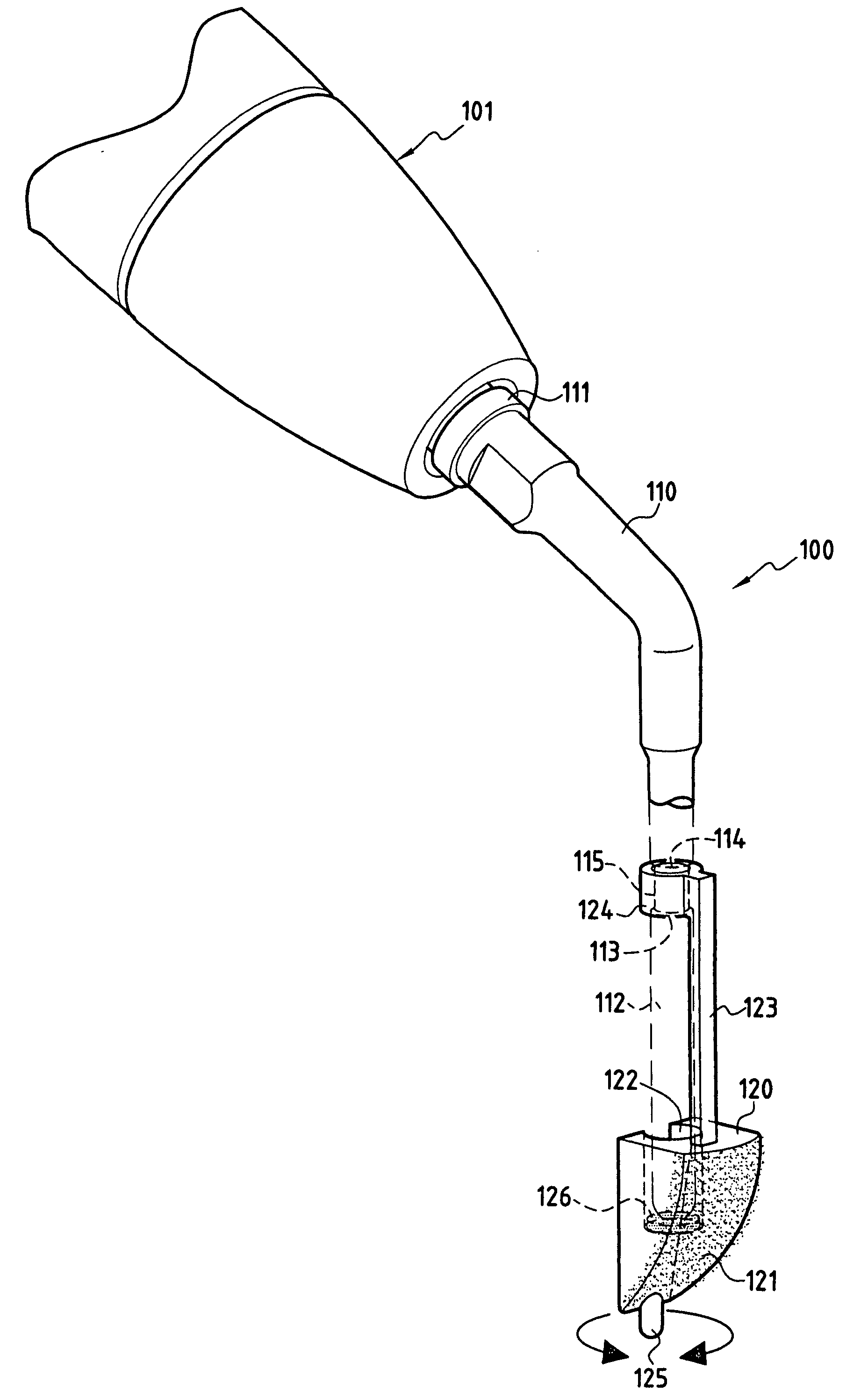
[0036]FIG. 3 illustrates a tip 100 in accordance with a first embodiment of the present invention. The tip 100 comprises a body 110 made up of a single piece, for example made of metal, which has a first end 111 adapted to be fixed to a handpiece 101. In a well-known manner, the handpiece 101 is a sound or ultrasound vibration generator which can comprise a transducer (not depicted) formed for example from a piezoelectric material and mechanically coupled rigidly to the tip so as to transmit vibratory waves thereto. The second end of the body 110 forms a tool holder 112 which is intended to reproduce the vibrations transmitted by the handpiece. The tool holder 112 is rigidly assembled with the body of the tip 110 (nut and bolt system, welding or simple extension of the tip).

[0037]In accordance with the invention, a tool 120 is disposed at the tool holder 112. The tool 120 comprises a cavity 122 serving as a housing for the end of the tool holder 112. The tool 120 is connected to the...


PUM


Abstract

Vibratory tip (100) comprising a body (110) having a first end (111) adapted to be mechanically coupled rigidly with a surgical handpiece (101) generating vibrations and a second end to which there is fixed a tool holder (112) intended to reproduce the vibrations transmitted by the handpiece. The tip furthermore comprises a tool (120) comprising a working area (121). In accordance with the invention, the tool (120) is mounted able to rotate freely with the tool holder (112), which allows the tool to adjust itself automatically in order to remain in contact with the tooth and position the working area on the entire periphery of the tooth with a single tip. The tool preferably comprises two working areas to improve keeping and guiding the tool on the surface of the tooth to be treated.

Description

FIELD AND BACKGROUND OF THE INVENTION [0001]The present invention concerns dental treatment instruments and more particularly vibrational instruments, such as scaling instruments, which comprise instruments vibrating at audible or ultrasonic frequencies.[0002]This type of instrument, depicted in FIG. 1A, is essentially made up of a handpiece 1 comprising a transducer mechanically coupled rigidly to a vibrating instrument called a “tip”10, the handpiece being connected to a vibration generator (not depicted). Examples of such tips are described in particular in the documents U.S. Pat. No. 6,312,256 and U.S. Pat. No. 4,283,175.[0003]The tip is an interchangeable part that has a great variety of shapes depending on the use for which it is intended (e.g. scaling: elimination of solid deposits, polishing: elimination of biofilms, grinding: cavities or prosthesis preparations).[0004]As illustrated in FIG. 1A, the existing devices comprise a body 11, most often metallic, one end thereof be...

Claims


Application Information

Patent Timeline
Patent Type & Authority Applications(United States)
IPC IPC(8): A61C1/07
CPCA61C3/03A61C17/20
Inventor LESAGE, PATRICK
Owner LESAGE
Why Eureka
Try Eureka