Method for monitoring seismic events

a seismic event and method technology, applied in seismology for waterlogging, instruments, reradiation, etc., can solve the problems of difficult interpretation of microseismic signals and inability to readily observe hydrofracturing processes

Active Publication Date: 2009-02-19
SCHLUMBERGER TECH CORP
View PDF11 Cites 38 Cited by
  • Summary
  • Abstract
  • Description
  • Claims
  • Application Information

AI Technical Summary

Benefits of technology

[0028]In the rotated coordinate system the signals become independent of at least one component of the moment tensor and hence can be evaluated or inverted fro the remaining components. It is seen as an advantage of the present method over existing methods of determining the moment tensor that the missing component has no influence on the values of remaining component. No assumption such as zero trace or non-volumetric source mechanisms have to be made to derive the values of the remaining components.

Problems solved by technology

The hydraulic fracturing processes cannot be readily observed, since they are typically thousands of feet or meters below the surface of the earth.
Apart from the problem of detecting the often faint microseismic events as such, the interpretation of microseismic signals is difficult as often neither the source location nor the source signature or characteristics are known prior to a processing of the measurements.

Method used


Image

  • Method for monitoring seismic events
  • Method for monitoring seismic events
  • Method for monitoring seismic events

Examples


Embodiment Construction

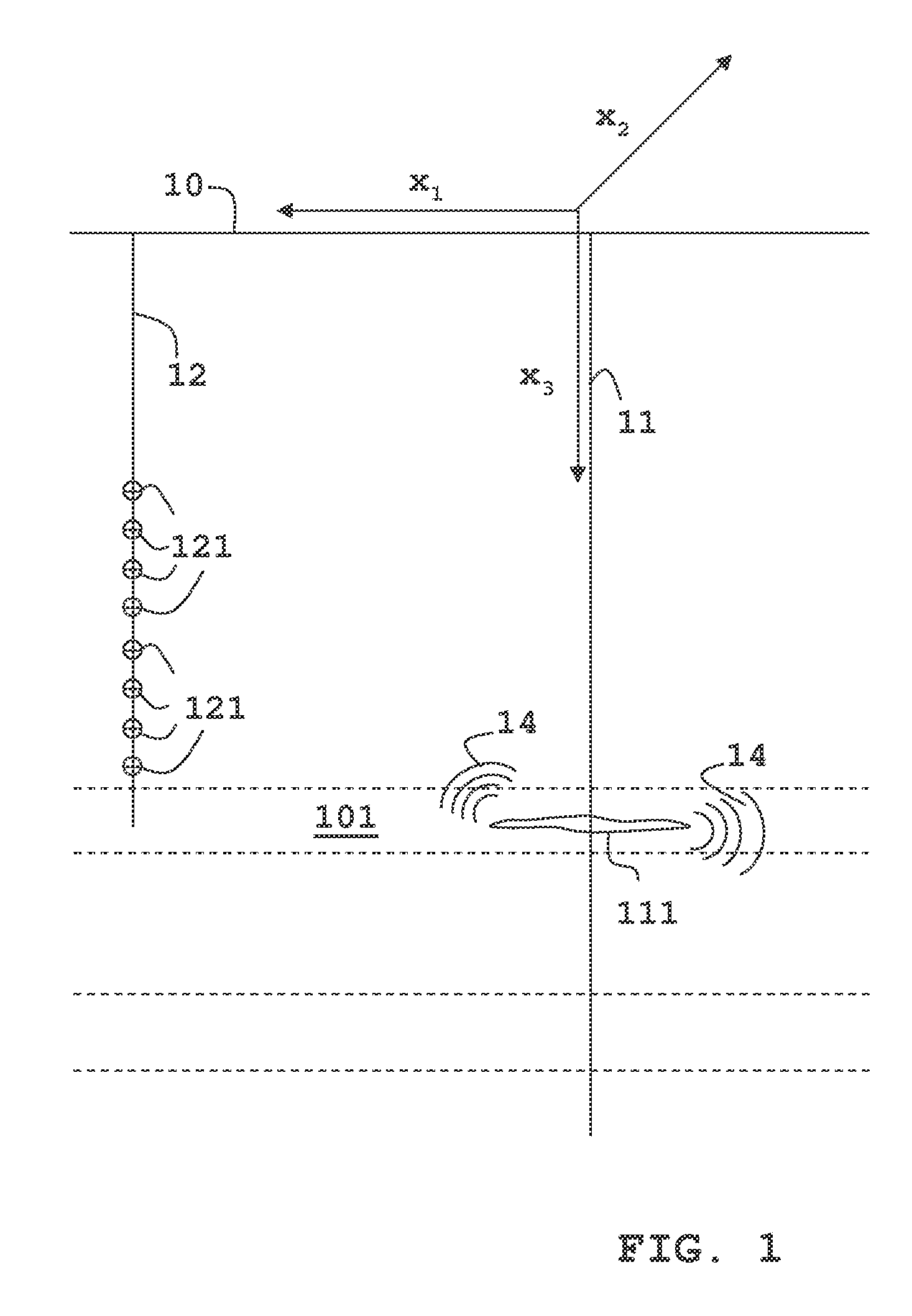
[0039]A typical operational setting for monitoring hydraulic fracturing in accordance with an example of the present invention is illustrated in FIG. 1.

[0040]This figure shows an example of a treatment well 11 and a geophone array 121 of 8 three-component geophones located in a neighboring well 12 the so-called monitoring well. The borehole is located at an approximate distance of 250 meters in horizontal direction with an azimuth of 335° from the source hypocenter. The lowest geophone is 10 meter above the depth of the source and the geophone spacing is 30 meters (i.e., the highest geophone is 220 meters above the source).

[0041]During the fracturing operation a fluid is pumped from the surface 10 into the well 11 causing the surrounding formation in a hydrocarbon bearing layer 101 to fracture. Acoustic waves 14 generated by the fracture 111 propagate through the earth and are recorded by the three-components geophones of the array 121.

[0042]The present invention assumes that the si...


PUM


Abstract

A microseismic method of monitoring fracturing operation or other microseismic events in hydrocarbon wells is described using the steps of obtaining multi-component signal recordings from a single monitoring well in the vicinity of a facture or event; and rotating observed signals such that they become independent of at least one component of the moment tensor representing the source mechanism and performing an inversion of the rotated signals to determine the remaining components.

Description

[0001]Embodiments of this invention relate to methods for monitoring seismic events, particularly microseismic events caused or relating to human activity in a subterranean reservoir or borehole. More specifically, but not by way of limitation, embodiments of the present invention relate to such methods for determining source characteristics and location of such events.BACKGROUND OF THE INVENTION[0002]Seismic monitoring is known as a method with an observation horizon that penetrates far deeper into a hydrocarbon reservoir than any other method employed in the oilfield industry. It has been proposed to exploit the reach of seismic methods for the purpose of reservoir monitoring.[0003]In conventional seismic monitoring a seismic source, such as airguns, vibrators or explosives are activated and generate sufficient acoustic energy to penetrate the earth. Reflected or refracted parts of this energy are then recorded by seismic receivers such as hydrophones and geophones.[0004]In micros...

Claims


Application Information

Patent Timeline
Patent Type & Authority Applications(United States)
IPC IPC(8): G01V1/28G01V9/00
CPCG01V2210/123G01V1/008
Inventor JECHUMTALOVA, ZUZANAEISNER, LEO
Owner SCHLUMBERGER TECH CORP
Why Eureka
Try Eureka