System for Determining a Vehicle Load

Inactive Publication Date: 2009-02-19
TRINITY COLLEGE DUBLIN
View PDF2 Cites 14 Cited by
  • Summary
  • Abstract
  • Description
  • Claims
  • Application Information

AI Technical Summary

Benefits of technology

[0042]The system of the invention provides a number of advantageous effects including:[0043]determination of the static axle load of a vehicle while the vehicle is in motion;[0044]using vehicle mounted instrumentation to determine static load;[0045]using measurements of axle strain to determine the axle load;[0046]using strain gauge transducers to transduce axle strain;[0047]using measurements of longitudinal strain to determine axle strain;[0048]using axle load measurements to determine static vehicle load;[0049]using axle load measurements to determine axle load transmitted to road surface;[0050]solving the inverse strain-force problem to determine the load from measurements of strain;[0051]use of 3-D Finite Element modelling to determine the strain distribution in an axle housing in order to find the optimum locations to site strain transducers;[0052]use of Finite Element modelling to determine absolute strain levels at specific sites on the axle;[0053]using multiple data acquisition nodes to digitize strain levels;[0054]connecting WIM nodes using a Controller Area Network bus to fleet management controller;[0055]off line calculation of the axle loads and vehicle weight and load distribution from axle strain data provided to a central server via a communications link.
[0043]determination of the static axle load of a vehicle while the vehicle is in motion;
[0045]using measurements of axle strain to determine the axle load;
[0049]using axle load measurements to determine axle load transmitted to road surface;

Problems solved by technology

Axle loads (forces) transmitted by a vehicle to a road are known to cause damage to the road surface.
It is known that heavy goods vehicles cause the majority of road damage.

Method used


Image

  • System for Determining a Vehicle Load
  • System for Determining a Vehicle Load
  • System for Determining a Vehicle Load

Examples


example

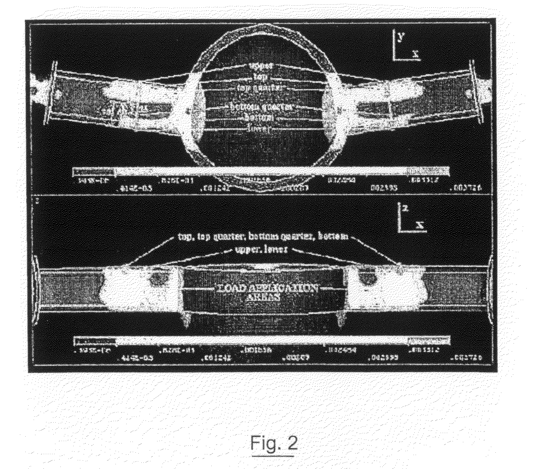
[0110]A finite element analysis (FEA) of a truck axle from a DAF tractor unit was carried out and the strain distribution determined is shown in FIG. 2.

[0111]The strain intensity plot highlighted three areas of high strain in the structure, one directly-beneath the point of application of the load and the others at the quarter points on the front face of the axle arm directly beneath the point of load application. Placing the strain gauges 2 directly beneath the point of load application may be impractical. Instead further investigation was performed focussing on the strain distribution within the front wall.

[0112]Static analysis in the range of expected axle loads showed a linear increase in strain, both in the vertical and longitudinal directions, with increasing payload. The strains versus payload in the longitudinal direction (X direction) and the vertical direction (Y direction) are shown in FIG. 3 and FIG. 4 respectively.

[0113]From these results the invention demonstrates that...


PUM


Abstract

A system (1) for determining a load of a vehicle such as a HGV. The system (1) comprises a plurality of strain gauges (2) mounted on each axle (3, 4) of the HGV. Each strain gauge (2) is arranged parallel to the longitudinal axis A-A of the axles (3, 4) to measure the strain exerted on each axle (3, 4) in a direction substantially parallel to the longitudinal axis A-A of each axle (3, 4). The strain gauges (2) are mounted on the axles (3, 4) at locations on the axles (3, 4) at which the axles (3, 4) exhibit a substantially linear strain-load relationship. These locations are determined, by performing a finite element analysis of the axles (3, 4). The system (1) also comprises a master control unit (5), carried on-board the HGV5 for calculating the HGV load responsive to the longitudinal strain measured by the strain gauges (2). The load exerted by the HGV on the road surface may then be calculated responsive to the calculated HGV load. The strain gauges (2) may be employed to measure in real-time the longitudinal strain exerted on the nodes (3, 4) of the HGV while the HGV is moving, and the master control unit (5) may be employed to calculate in real-time the HGV load while the HGV is moving. The system (1) further comprises a transmitter for transmitting information from the HGV to a central server at a location remote from the HGV.

Description

INTRODUCTION[0001]This invention relates to a system for determining a vehicle load and to a method of determining a vehicle load. This invention is particularly suitable for determining the load of a heavy goods vehicle (HGV).[0002]A considerable amount of time and money is spent annually on repair and maintenance of roads internationally. Axle loads (forces) transmitted by a vehicle to a road are known to cause damage to the road surface. It is known that heavy goods vehicles cause the majority of road damage. This axle-force or load has two components; a static component, which is determined by the weight of the vehicle plus the payload, and a dynamic component, evident when the vehicle is in motion. The dynamic component is time dependent and is driven by excitation sources external to the vehicle, for example road surface roughness.[0003]This invention is aimed at providing a system and method for determining a vehicle load, in one particular case for determining a vehicle load...

Claims


Application Information

Patent Timeline
IPC IPC(8): G01L5/00G01G19/08
CPCG01G19/12G01G23/3742G01G23/3728
Inventor GERAGHTY, THOMAS DERMOTBASU, BISWAJIT
Owner TRINITY COLLEGE DUBLIN
Why Eureka
Try Eureka