Method for Expanding Audio Signal Bandwidth

a technology of audio signal and bandwidth, applied in the field of audio signal processing, can solve the problems of reducing the accuracy of audio signals, and reducing the quality of signals,

Inactive Publication Date: 2009-02-19
MITSUBISHI ELECTRIC RES LAB INC
View PDF7 Cites 40 Cited by
  • Summary
  • Abstract
  • Description
  • Claims
  • Application Information

AI Technical Summary

Benefits of technology

The patent describes a method that solves the problem of polyphony in complex sounds by automatically separating out consistent components and recombining them. This helps to expand the frequencies of individual components and avoids the problems of the prior art.

Problems solved by technology

The technical problem addressed in this patent text is the need for a method to expand the bandwidth of audio signals, particularly for complex polyphonic signals, while maintaining high quality results. Existing methods have limitations in effectively recovering missing frequency information and can introduce undesirable artifacts, such as spurious spectral peaks. The proposed method aims to overcome these limitations and provide quality results for both simple and complex signals.

Method used


Image

  • Method for Expanding Audio Signal Bandwidth
  • Method for Expanding Audio Signal Bandwidth
  • Method for Expanding Audio Signal Bandwidth

Examples


Embodiment Construction

[0025]Latent Component Analysis

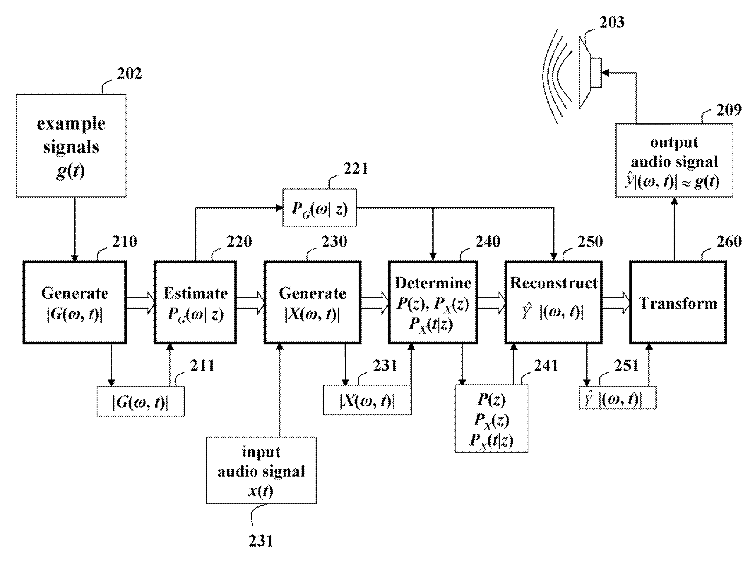
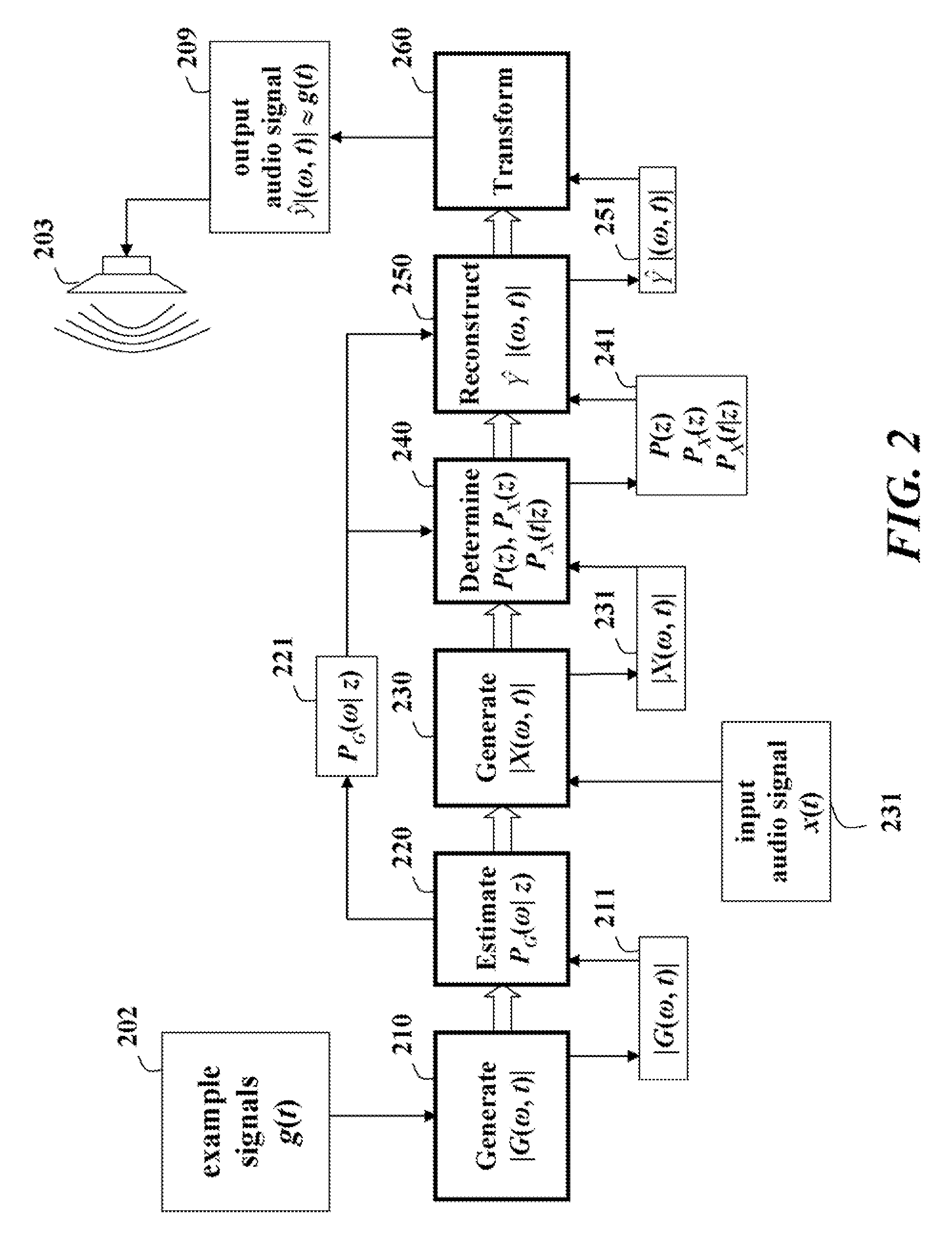
[0026]We use probabilistic latent component analysis (PLCA) to represent a multi-state generalization of a magnitude spectrum of an audio signal. The audio signal is in the form of time series data x(t) with a corresponding time-frequency decomposition X(ω,t). The decomposition can be obtained by a short-time Fourier transform (STFT).

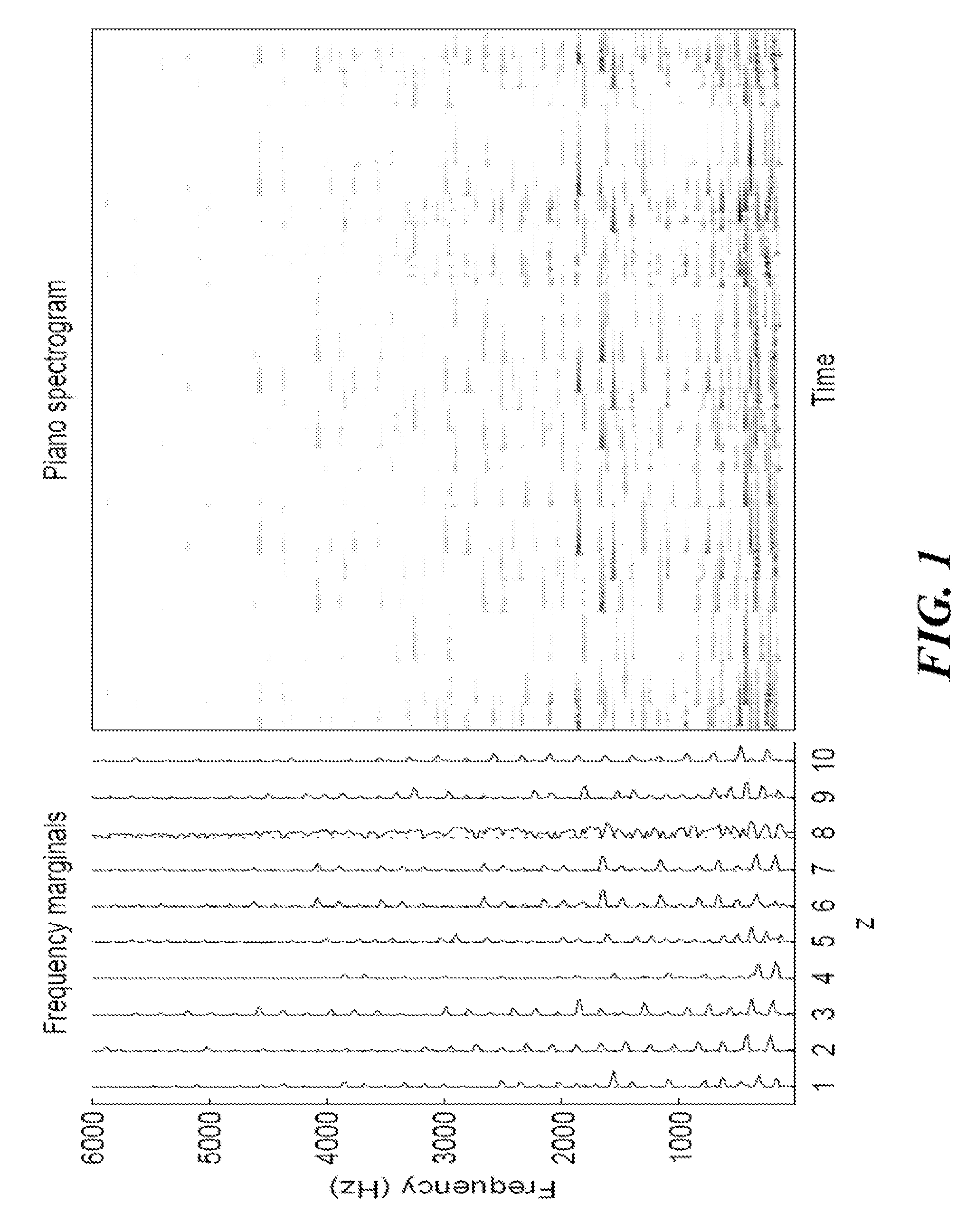
[0027]A magnitude of the transform |X(ω,t)| can be interpreted as a scaled version of a two-dimensional probability P(ω,t) representing an allocation of frequencies across time. The marginal probabilities of this distribution along frequency ω and time t represent, respectively, an average spectral magnitude and an energy envelope of the audio signal x(t).

[0028]We decompose the probability P(ω,t) into a sum of multiple independent, components:

P(ω,t)=ΣεP(z)Pz(ω,t),

where the probability P(z) is a probabilistic ‘weight’ of the zth component Pz(ω,t) in a polyphonic mixture of audio signals. The components Pz(ω,t) can be entire...


PUM


Abstract

A method expands a bandwidth of an audio signal by determining a magnitude time-frequency representation |G(ω,t) for example audio signals g(t). A set of frequency marginal probabilities PG(ω|z) 221 are estimated from |G(ω,t)|, and a magnitude time-frequency representation |X(ω,t)| is determined from an input signal audio signal x(t). Probabilities P(z), PX(z) and PX(t|z) are determined using PG(ω|z)|X(ω,t)|. |Ŷ(ω,t)| is reconstructed according to PzPX(z)PG(ω|z)PX(t|z), and Ŷ(ω,t)| is transformed to a time domain to obtain a high-quality output audio signal ŷ(t) corresponding to the input audio signal x(t).

Description


Claims


Application Information

Patent Timeline
Owner MITSUBISHI ELECTRIC RES LAB INC
Why Eureka
Try Eureka