Eureka AIR delivers breakthrough ideas for toughest innovation challenges, trusted by R&D personnel around the world.

Awning clamping assembly

a clamping assembly and awning technology, applied in the field of awnings, can solve the problems of excessively loose material exposed to the effects of wind, loud and annoying sounds, and most, if not all, are either too complex in structure and/or inadequate in size and function to operate effectively and achieve the intended effect, and achieve superior control over the rapid and annoying flapping of the canopy material, the effect of maximizing its fundamental effect and extending the structur

Inactive Publication Date: 2009-02-26
VALTERRA PRODS
View PDF9 Cites 1 Cited by
  • Summary
  • Abstract
  • Description
  • Claims
  • Application Information

AI Technical Summary

Benefits of technology

"The present invention is a clamping assembly for securing the canopy of a retractable awning mounted on a recreational vehicle. The assembly includes retractable support arms, clamp members with projecting clamping flanges, lever arms, and a spring-loaded mechanism for adjusting the tightness of the clamping flanges. The clamping assembly maximizes its effectiveness by engaging a larger surface area of the canopy material and provides superior control over the rapid and annoying flapping of the canopy material. It is easy and cost-effective to manufacture and can be relocated at various positions along the canopy edges with ease and convenience."

Problems solved by technology

However, the side edges of the canopy material are not typically secured to the braces leaving the relatively loosely held material exposed to the effects of the wind.
When the winds pick up, they tend to cause the canopy material to rapidly flap up and down, which creates loud and annoying sounds.
Yet most, if not all, are either too complex in structure and / or too inadequate in size and function to operate effectively and achieve the intended objective.

Method used


Image

  • Awning clamping assembly
  • Awning clamping assembly
  • Awning clamping assembly

Examples


Embodiment Construction

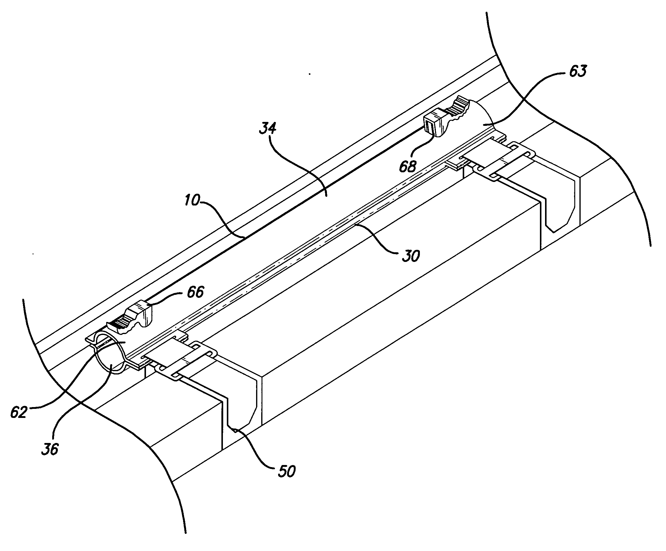
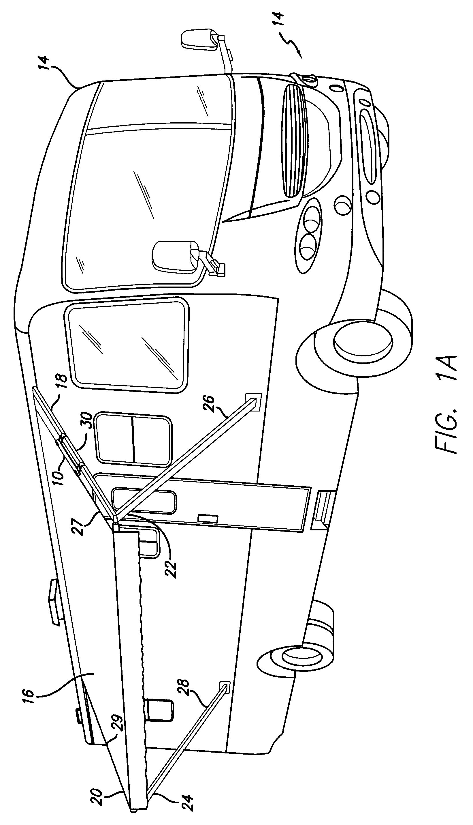
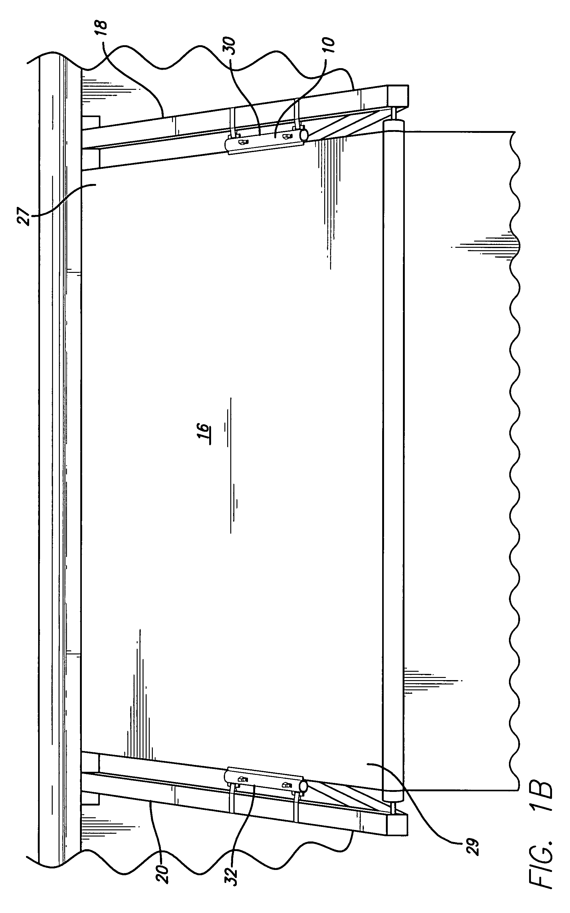
[0035]The present invention provides a clamping assembly 10 shown in FIGS. 1A and 1B mounted to one edge of canopy 16 of recreational vehicle 14. Clamping assembly 10 is provided to secure the material of canopy 16 to support braces 22 and 24, which are the principal components of a support sub-assembly comprising upper support braces 18 and 20 and lower support braces 26 and 28.

[0036]In the preferred embodiment employing two separate clamping assemblies along the opposing side edges 27 and 29 of canopy 16, first clamp member 30 and second clamp member 32, which may be elongated and tubular in form, are provided with each having a top section 34 and a bottom section 36.

[0037]Top section 34 has an outside surface 38, an inside surface 40, a back surface 37 and a front surface 39. Bottom section 36 has an outside surface 41, an inside surface 42, a back surface 43 and a front surface 44. Protruding from one end of back surface 37 of top section 34 is member 45 having opening 46. Protr...


PUM


Abstract

A clamping assembly for securing the canopy of a retractable awning mounted on a recreational vehicle, including one or more clamp members, each having a top section and a bottom section positioned in face opposed relation with each section having a back surface and a front surface. Each back surface includes a protruding member with an opening adapted, when aligned, to receive a means to attach the clamp member to support arms. The front surfaces form a pair of projecting face opposed clamping flanges with a space in between the two to engage the canopy material. Also provided is a pair of spring-loaded lever arms adapted for pivotal movement between a vertical position to enable the flanges to engage the canopy material in a releasable grip and a horizontal position to enable the flanges to separate and release their grip on the canopy. Rotating the lever arms in opposite directions act to adjust the tightness of the grip the flanges have on the canopy material.

Description

BACKGROUND OF THE INVENTION[0001]1. Field of the Invention[0002]The present invention relates generally to the field of awnings used with recreational vehicles and, more particularly, to an improved assembly for grabbing and stabilizing an awning canopy to eliminate or at least minimize the flapping of the canopy material and the loud and annoying flapping sounds normally associated therewith.[0003]2. Description of the Prior Art[0004]A preliminary patentability and novelty search in connection with the present invention has revealed the existence of the following U.S. patents:[0005]1. U.S. Pat. No. D386,076: This reference is directed to the ornamental design for an awning clamp as shown in FIGS. 1-6. The structure is a U-shaped clamp with textured jaws to grip the awning. The clamp is apparently opened by being resilient and closed by means of a thumb screw located halfway between the jaws and the U bend.[0006]2. U.S. Pat. No. 5,369,850: This reference is directed to a dual grip c...

Claims


Application Information

Patent Timeline
Patent Type & Authority Applications(United States)
IPC IPC(8): E04F10/02
CPCE04F10/0614Y10T24/3439E04F10/0666E04F10/0644
Inventor LUNDER, DENNIS
Owner VALTERRA PRODS
Why Eureka
Eureka Blog
Learn More