Optical grain sorter

a sorter and optical technology, applied in the field of optical grain sorters, can solve the problems of operator failure to notice defective grains, inability to discriminate between normal grains and defective grains displayed on the monitor, and inconvenient setting of sorting level

Inactive Publication Date: 2009-02-26
SATAKE CORP
View PDF10 Cites 44 Cited by
  • Summary
  • Abstract
  • Description
  • Claims
  • Application Information

AI Technical Summary

Benefits of technology

[0013]An object of the present invention is to provide an optical grain sorter capable of enabling an operator to clearly identify defective grains on a monitor screen of a display device.
[0014]Another object of the present invention is to provide an optical grain sorter capable of enabling an operator to clearly identify each of defective grains having light colored portions occupying a certain area or larger colored portions and defective grains having darker colored portions.
[0015]Still another object of the present invention is to provide an optical grain sorter capable of enabling an operator to check whether or not air jet nozzles corresponding to the positions of defective grains in a multiplicity of air jet nozzles prepared are correctively selected.
[0024]Preferably, operative nozzle indication means are provided in the control means to also produce on the monitor screen of the display device a display indicating the position of the air jet nozzles selected by the control means to operate. This display enables the operator to determine whether or not the air jet nozzles corresponding to the fall-down paths through which the defective grains fall are correctly selected by the control means to separate the defective grains from the normal grains.
[0025]The optical grain sorter of the present invention enables the operator to easily and reliably check on the monitor screen the degree of defectiveness of the defective grains to be separated from the normal grains, i.e., on what criteria does the sorter operated by the operator evaluate the light colored portions and the dark colored portions in sorting out the defective grains. Therefore, the operator can easily perform a simulation for setting the threshold values in the defective grain removal means and the threshold value in the contour processing means and can accurately and efficiently determine the threshold values set in the optical grain sorter.
[0026]If means for storing image data displayed several past batches of image data displayed on the display device together with the threshold values set in correspondence with the past batches of image data and evoking the data when required is provided, the efficiency of the above-described simulation can be improved. In such a case, displays can be produced in a convenient manner, for example, in such a manner that the present data and past batches of data are simultaneously displayed in divided sections on the screen.

Problems solved by technology

However, while a certain degree of sorting suffices for avoiding any problem in terms of commodity value, there is a possibility of inappropriate setting of the level of sorting in some case of use of an optical grain sorter, depending on the kind or grade of grain or on the degree of cleaning.
However, it has a problem in terms of image display technique and, hence, the drawback of not facilitating discrimination between normal grains and defective grains displayed on the monitor.
The images on the monitor are thus complicated, so that it is difficult to discriminate defective grains having light colored portions and defective grains having dark colored portions and there is a possibility of an operator failing to notice defective grains.
It is necessary to unfailingly sort out defective grains having dark colored portions in particular.
After the occurrence of failure to notice a defective grain having a dark colored portion and after the completion of sorting, the defective grain may be found in normal grains.
Such an incident leads to a considerable reduction in reliability of the sorting process.
The technique for the optical grain sorter described in Japanese Patent Laid-Open No. 2005-74412 also has a problem that an operator is uncertain as to whether or not defective grains are correctly separated by air jet nozzles for separating defective grains from normal grains.

Method used


Image

  • Optical grain sorter
  • Optical grain sorter
  • Optical grain sorter

Examples


Embodiment Construction

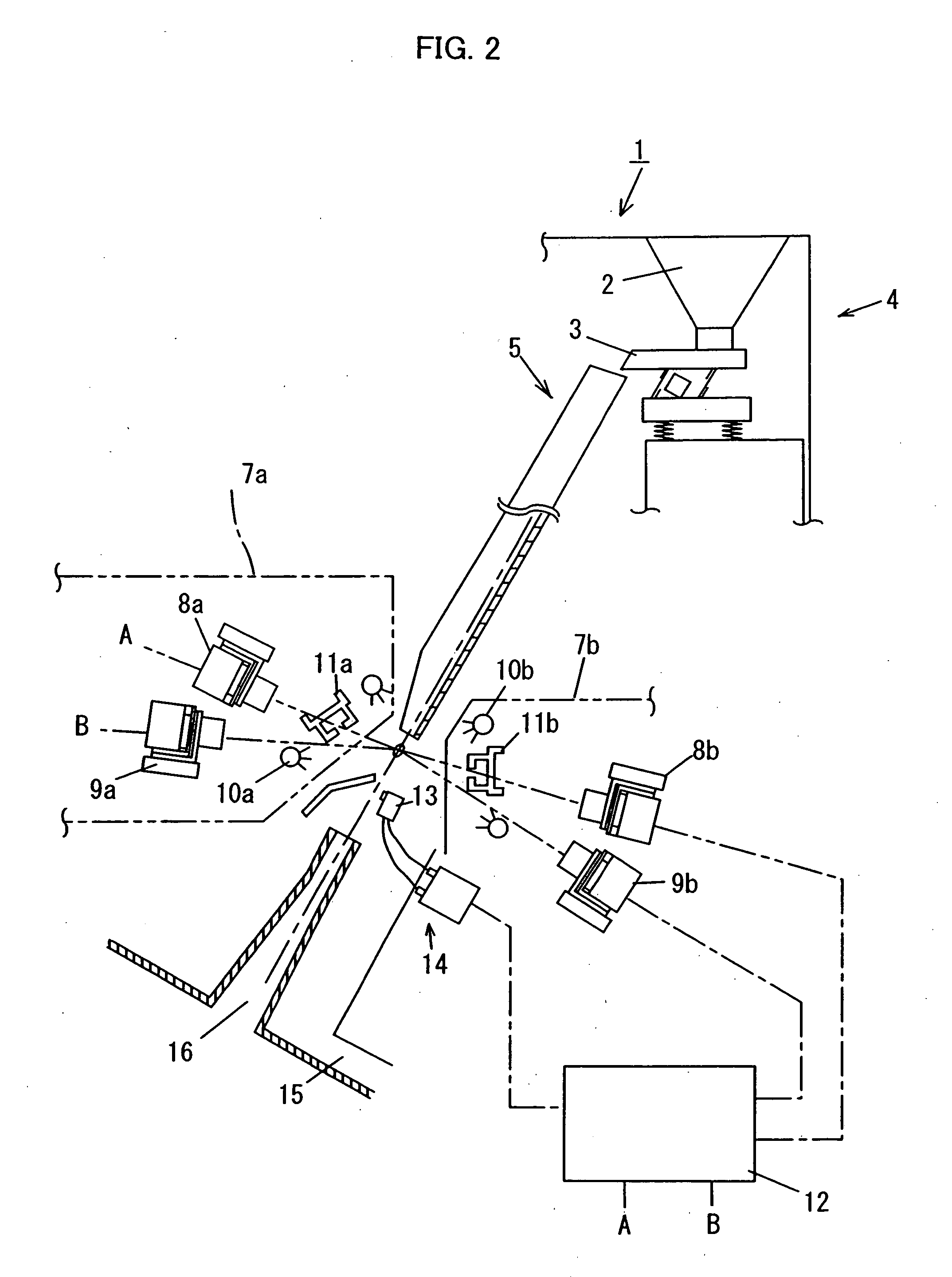
[0042]FIG. 2 schematically shows essential internal structural portions of an optical grain sorter 1 which is an embodiment of the present invention. The optical grain sorter 1 has, at an upper position therein, a grain supply portion 4 including a tank 2 and a vibrating feeder 3. Grains supplied from the grain supply portion 4 (polished grains in the present embodiment) flow continuously downward onto a slanting shoot 5 by gravity. On the slanting shoot 5 having a predetermined shape, grains can flow downward while spreading laterally widely. The grains are let fall from the lower end of the slanting shoot into the air by taking a multiplicity of columnar fall-down paths parallel to each other. In the present embodiment, the slanting shoot 5 has flat shooting surface, as shown in FIG. 3A. However, the shooting surface may have a multiplicity of flow-down grooves 6 each having a width close to the width W of grains, as shown in FIG. 3B. It is preferable to provide such grooves becau...


PUM


Abstract

A grain images obtained by CCD line sensors are processed by binarization processing to obtain contour images of grains and images of colored portions in the grains. The images are displayed on a monitor screen of an operating panel 30. The contour images and the images of the colored portions are displayed in a superposed state. Box frames generated by a highlight display circuit in control means 12 are simultaneously displayed by being superposed on the contour images having defective portions, thus producing a highlight display of defective grains. The defective grains include a grain having a light colored portion and a grain having a dark colored portion.

Description

BACKGROUND OF INVENTION[0001]1. Field of the Invention[0002]The present invention relates to an optical grain sorter used to sort out grains (defective grains) not normal in external appearance as a grain product from grain distributed on the market. More particularly, the present invention relates to an optical grain sorter of this kind arranged so that an operator can adjust a level of determination sensitivity (a threshold value set in the optical grain sorter) provided in the sorter for sorting normal grains (grains having a normal external appearance) and defective grains from each other, by seeing a display on a display device provided on the sorter.[0003]2. Description of Related Art[0004]In distribution of grain on the market, the commodity value should be improved by removing defective grains not normal in external appearance as grains. To do so, an optical grain sorter is used. However, while a certain degree of sorting suffices for avoiding any problem in terms of commodi...

Claims


Application Information

Patent Timeline
Patent Type & Authority Applications(United States)
IPC IPC(8): B07C5/342
CPCB07C5/3425G01N21/85B07C5/366Y10S209/932G01N21/00
Inventor IMAI, TAKESHITANAKA, NORIHIKO
Owner SATAKE CORP
Why Eureka
Try Eureka