
Image pickup device and image pickup control method

a technology of image pickup and control method, which is applied in the direction of optical radiation measurement, instruments, television systems, etc., can solve the problems of driver dazzle, effect exertion, driver image performance drop, etc., and achieve the effect of suppressing the increase in size and electric power consumption of illumination

Inactive Publication Date: 2009-02-26
ORMON CORP
View PDF7 Cites 20 Cited by
  • Summary
  • Abstract
  • Description
  • Claims
  • Application Information

AI Technical Summary

Benefits of technology

[0009]The present invention is one made in view of the situation like this, and is one making it possible to obtain the image in which the shadow of the driver's face is certainly suppressed, while suppressing the increases in the size and the electric power consumption of the illumination.

Problems solved by technology

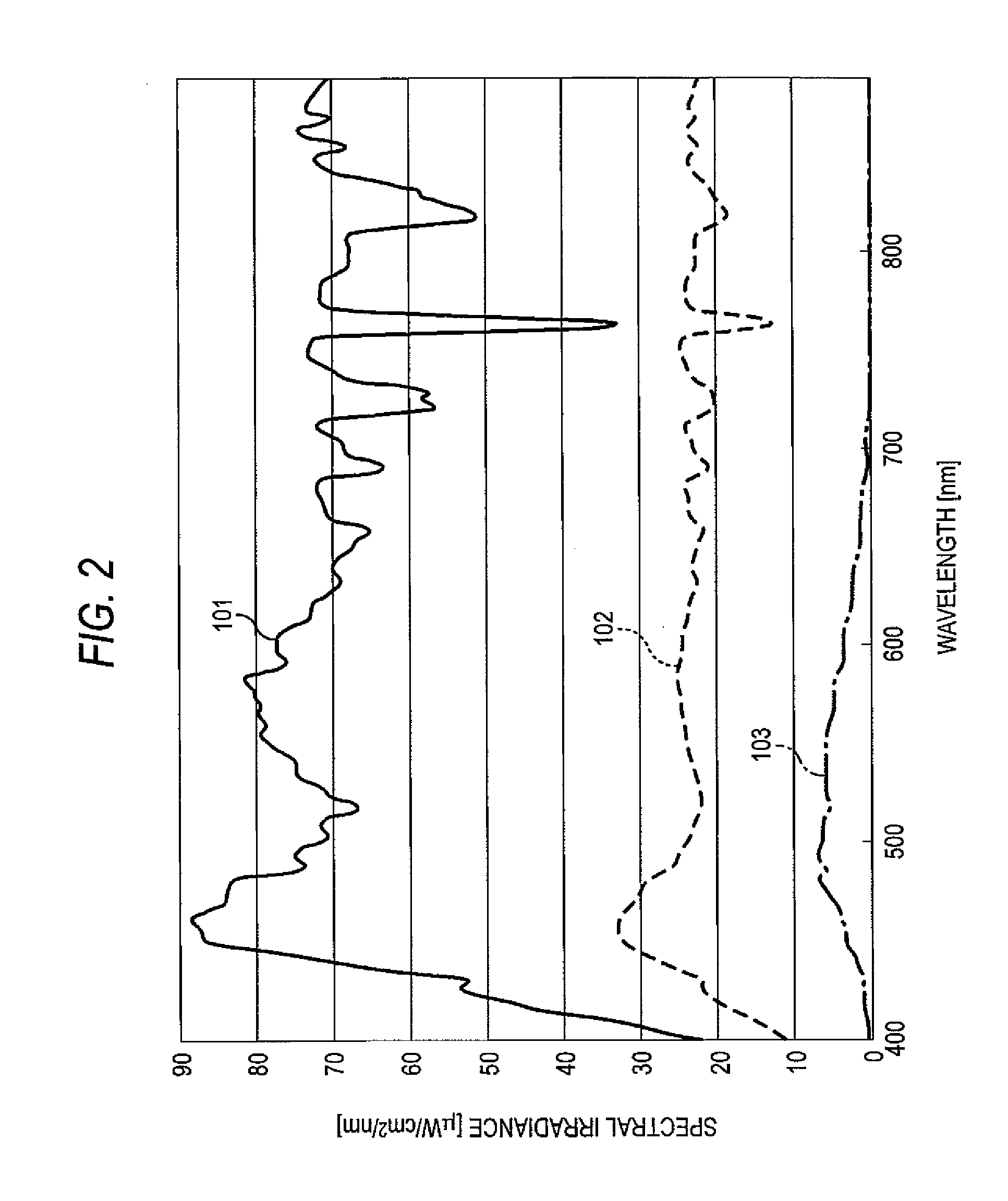
There is a case where, by this disturbance light, such phenomena occur that a deep shadow generates in the driver's face, a white spot occurs in the driver image by a light quantity excess, and the light directly irradiates the image pickup device and thus hinders the image pickup, thereby bringing about a decrease in a performance of the image processing of the driver image.
In this case, although it is necessary to irradiate a light more intensive than the sunlight which is one of the disturbance lights, if the light more intensive than the sunlight is irradiated, there is a fear that such adverse effects are exerted that the driver is dazzled, and an injury is given to an eye of the driver.
However, since the sunlight is very intensive, in order to obtain, in the invention described in the Patent Document 1, an image in which the shadow of the driver's face is certainly suppressed, it is necessary to increase the number of the light emitting diodes and, as a result, a size and an electric power consumption of the illumination increase.

Method used


Image

  • Image pickup device and image pickup control method
  • Image pickup device and image pickup control method
  • Image pickup device and image pickup control method

Examples


Embodiment Construction

[0048]Hereunder, by referring to the drawings, there is explained about an embodiment of the present invention.

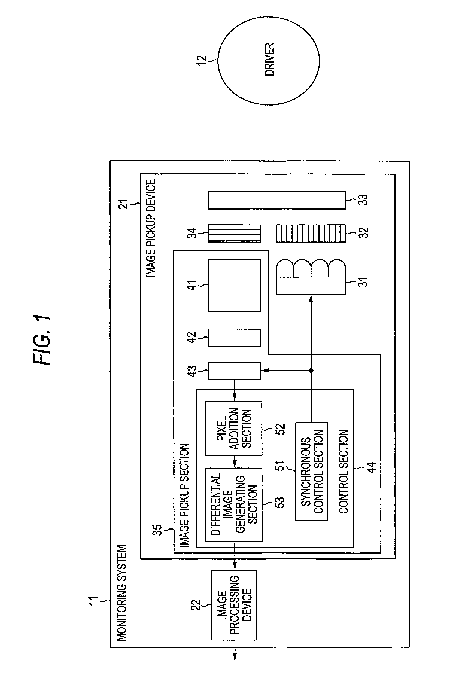
[0049]FIG. 1 is a block diagram showing one embodiment of a monitoring system to which the present invention was applied. A monitoring system 11 in FIG. 1 monitors a driver 12 driving a vehicle (hereafter, called own vehicle as well) in which there is provided the monitoring system 11, and performs a detection of, e.g., the side look, the sleep in siting position, or the like of the driver 12, and performs a certification of the driver 12. And, the monitoring system 11 outputs its result to a device in a post-stage. The monitoring system 11 is constituted so as to include an image pickup device 21 and an image processing device 22.

[0050]The image pickup device 21 image-picks-up the face of the driver 12 sitting on a driver's seat of the own vehicle from an approximately front direction while synchronizing with a flickering of an illumination 31, and takes a difference betwe...


PUM


Abstract

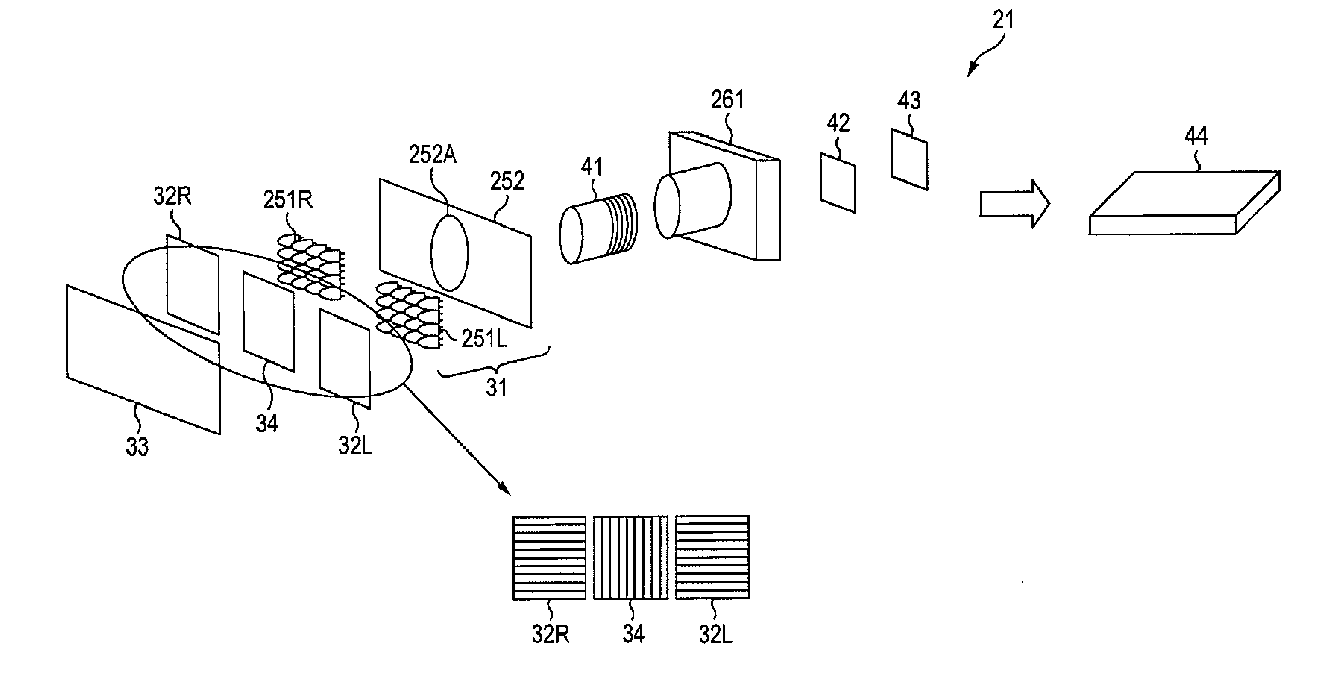
An image in which a shade of a driver's face is certainly suppressed is to be obtained, while suppressing increases in a size and an electric power consumption of an illumination. An illumination pulse-lights an illumination light which is an infrared light whose peak wavelength is 940 nm, under a control of a synchronous control section. The illumination light is irradiated to a driver through a polarizing filter and a visible light interruption filter. Reflex lights of the illumination light and a disturbance light, which were reflected by the driver, enter to an infrared BPF, in which a center wavelength is 940 nm, through the visible light interruption filter, a polarizing filter 34 and an optical lens. An image pickup element image-picks-up a light which transmitted through the infrared BPF. A synchronous control section controls such that a lit term of the illumination synchronizes with an exposure time of the image pickup element. The present invention can be applied, e.g., to a monitoring device of the driver.

Description

BACKGROUND OF THE INVENTION[0001]1. Field of the Invention[0002]The present invention relates to an image pickup device and an image pickup control method, and relates especially to an image pickup device and an image pickup control method, which are used in an image pickup of a driver in a vehicle.[0003]2. Description of Related Art[0004]In recent years, in order to prevent an accident by a side look or a sleep in a sitting position, there is advanced a development in a monitoring device which monitors the driver by image-picking-up a face of the driver driving the vehicle, and applying a predetermined image processing to an image-picked-up image (hereafter, called a driver image as well).[0005]By the way, a light environment in a vehicle chamber during running always fluctuates by a light (hereafter, called a disturbance light), such as sunlight, street lamp and store's illumination in roadside, which enters from a vehicle outside. There is a case where, by this disturbance light,...

Claims


Application Information

Patent Timeline
Patent Type & Authority Applications(United States)
IPC IPC(8): H04N5/33H04N23/75H04N23/76
CPCH04N5/2354H04N23/74
Inventor OTA, SHUNJITAMANAHA, HAJIMEOMOTO, YASUMICHI
Owner ORMON CORP
Learn More