Data storage systems and methods having block group error correction for repairing unrecoverable read errors

a data storage system and error correction technology, applied in error detection/correction, redundancy hardware error correction, instruments, etc., can solve the problems of data stored on disks being subject to various types of storage errors, data loss from isolated areas of the disk, data loss of all or substantially all data stored on the disk

Inactive Publication Date: 2009-02-26
PANASAS INC
View PDF10 Cites 58 Cited by
  • Summary
  • Abstract
  • Description
  • Claims
  • Application Information

AI Technical Summary

Benefits of technology

[0011]The method may further include receiving an error message if the single physical storage disk is unable to read one or more failed data or coding blocks associated with a given error correction group; in response to the error message, attempting to read a remainder of the data and coding blocks in the given error correction group; and if a sufficient number of the remainder of the data and coding blocks and coding blocks are successfully read, computing a corrected version of the one or more failed data or coding blocks from at least part of the remainder of the data and the coding blocks.
[0012]Moreover, the method may further comprise using the corrected version of the one or more failed data or coding blocks to rewrite an unreadable addressable block, optionally to a spare addressable block on the single physical storage disk, thereby repairing a fault associated with the error message.

Problems solved by technology

However, data stored on disks are subject to various types of storage errors.
For example, a catastrophic disk failure may be result in the loss of all, or substantially all, data stored on the disk.
Disk errors may also be localized, resulting in the loss of data from isolated areas of the disk, perhaps as small as a single sector.
Other read errors may be detected and corrected by the disk reading mechanism, for example, by retrying the operation, and result only in performance degradation.
The storage mechanism provided by RAID-1 is not the most economical or most efficient fault tolerance scheme.
Although RAID-1 storage systems are simple to design and provide 100% redundancy (and, hence, increased reliability) during disk failures, RAID-1 systems substantially increase the storage overhead because of the necessity to mirror everything.
As drive capacities have increased, nearly doubling in capacity every year, another common error source is the failure to read individual sectors from an otherwise healthy disk.
These errors are caused by defects in the recording media or recording faults, and are called “unrecoverable read errors” or “uncorrectable read errors” because the error correction codes on the drive are unable to correct the problem and the read operation fails.
When this occurs, some amount of data in a single failure correcting RAID array (ranging in size from a stripe to the entire array, depending on the implementation of the RAID controller) is irretrievably lost, leading to an indication being returned to the original requester (a user or application) that the data requested is unrecoverable.
Such an application / user-visible failure may involve, for example, the interruption of computing service, the need to restore data from back-up copies, and / or the loss of some previously written data.
However, these methods are expensive in terms of disk utilization and at best achieve a reduction in the frequency of user / application-visible errors.
The lack of an effective technique for correcting the combination of a failed disk drive and a URE during rebuild has led to the industry adoption of two-fault-tolerant RAID schemes.
However, these schemes suffer from common problems.
For example, RAID-6 doubles the parity overhead for the array, reducing usable capacity.
In addition, the amount of data that must be written to gain the performance advantages of a full stripe write is usually significantly larger to amortize the capacity overhead, which reduces throughput further for workloads that are not purely sequential.
However, there are a host of read errors that are not detectable or correctable by the reading mechanism.

Method used


Image

  • Data storage systems and methods having block group error correction for repairing unrecoverable read errors
  • Data storage systems and methods having block group error correction for repairing unrecoverable read errors
  • Data storage systems and methods having block group error correction for repairing unrecoverable read errors

Examples


Embodiment Construction

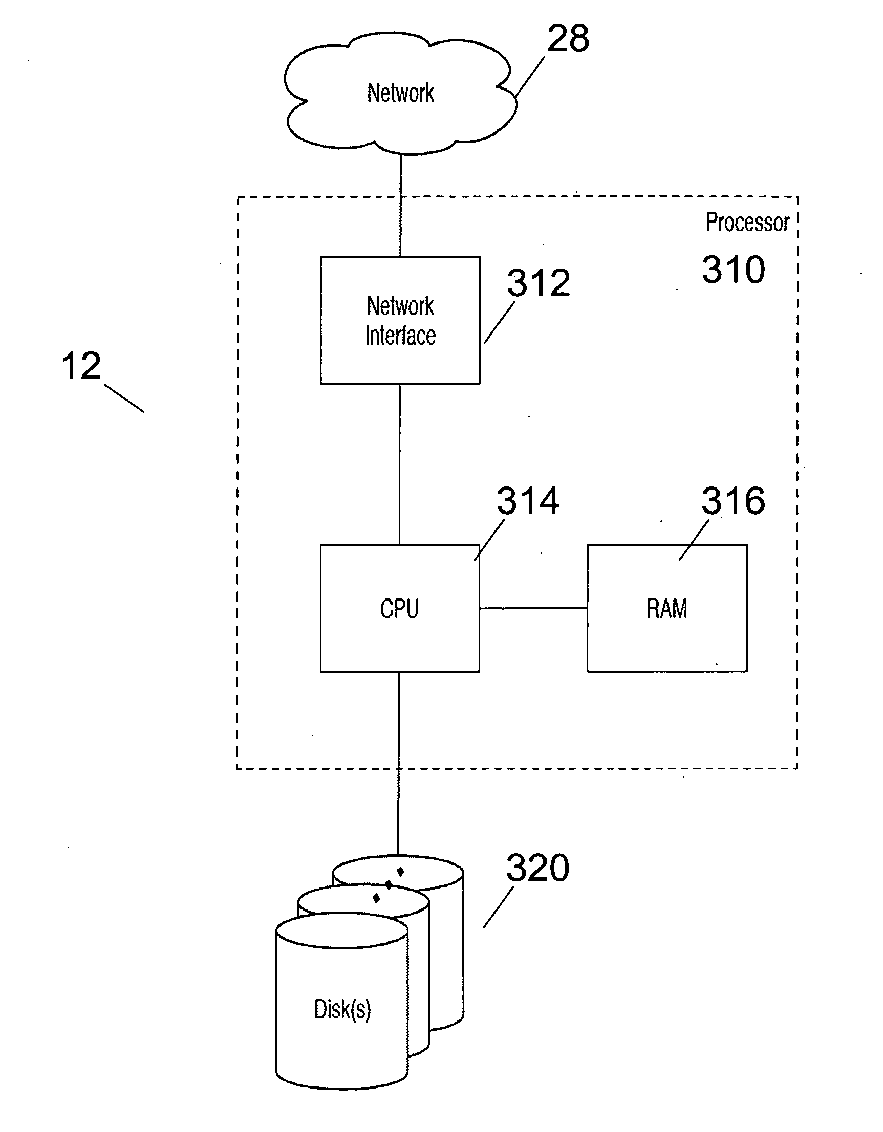
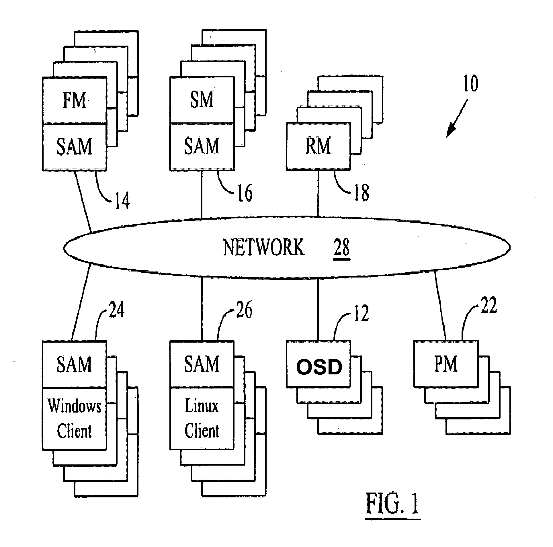
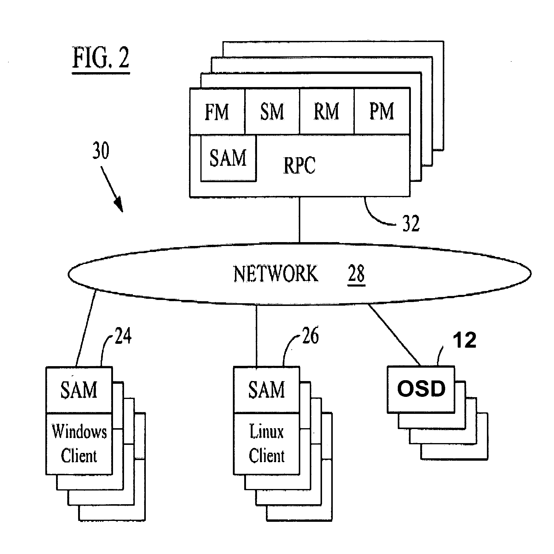
[0030]Reference will now be made in detail to the preferred embodiments of the present invention, examples of which are illustrated in the accompanying drawings. It is to be understood that the figures and descriptions of the present invention included herein illustrate and describe elements that are of particular relevance to the present invention, while eliminating, for purposes of clarity, other elements found in typical data storage systems or networks.

[0031]It is worthy to note that any reference in the specification to “one embodiment” or “an embodiment” means that a particular feature, structure or characteristic described in connection with the embodiment is included in at least one embodiment of the invention. The appearances of the phrase “in one embodiment” at various places in the specification do not necessarily all refer to the same embodiment.

[0032]Embodiments set forth below correspond to examples of object-based data storage implementations of the present invention....


PUM


Abstract

Data storage systems and methods perform error correction on a single physical storage disk. The technique includes arranging a plurality of addressable blocks on the single physical storage disk into error correction groups, wherein each error correction group includes N data blocks and M coding blocks. M is determined in accordance with a desired failure tolerance of the error correction groups and an error-correcting code. For each error correction group, error-correcting code data is computed across the N data blocks in the error correction group. The computed error-correcting coding data is stored in the M coding blocks in the error correcting group. The arranging, computing and storing steps are performed by a hardware or software component external to the single physical storage disk.

Description

[0001]This application claims the benefit of priority under 35 U.S.C. § 119(e) based on U.S. provisional application No. 60 / 950,433, filed on Jul. 18, 2007, which is incorporated herein in its entirety.FIELD OF THE INVENTION[0002]The present invention is directed to data storage systems and methods having block group error correction for facilitating file reconstruction and restoration.BACKGROUND OF THE INVENTION[0003]With increasing reliance on electronic means of data communication, different models to efficiently and economically store a large amount of data have been proposed. In a traditional networked storage system, a data storage device, such as a hard disk, is associated with a server or a server having a backup server. Access to the data storage device is available only through the server associated with that data storage device. A client processor desiring access to the data storage device would, therefore, access the associated server through the network and the server w...

Claims


Application Information

Patent Timeline
Patent Type & Authority Applications(United States)
IPC IPC(8): G06F11/20
CPCG06F2211/1092G06F11/1076
Inventor GIBSON, GARTH A.GRONKE, EDWELCH, BRENT B.
Owner PANASAS INC
Why Eureka
Try Eureka