Rigid wall panel system

Inactive Publication Date: 2009-03-05
GREENSTEEL TECH
View PDF7 Cites 30 Cited by
  • Summary
  • Abstract
  • Description
  • Claims
  • Application Information

AI Technical Summary

Benefits of technology

[0006]U.S. Pat. No. 6,167,624 (the “'624 patent”), issued to Lanahan et al., discloses a prior art foam panel having embedded metal studs. The lateral, vertical edges of the panel have a tongue-and-groove connector formed into the foam block. Adjacent panels are fitted together using the tongue-and-groove connectors. The '624 patent is representative of the deficiencies in the prior art, as no prior art wall panel known to the inventor has disclosed a method of joining the vertical edges of adjacent wall panels together u

Problems solved by technology

This method presents serious structural deficiencies insofar as the adjacent panels

Method used


Image

  • Rigid wall panel system
  • Rigid wall panel system
  • Rigid wall panel system

Examples


Embodiment Construction

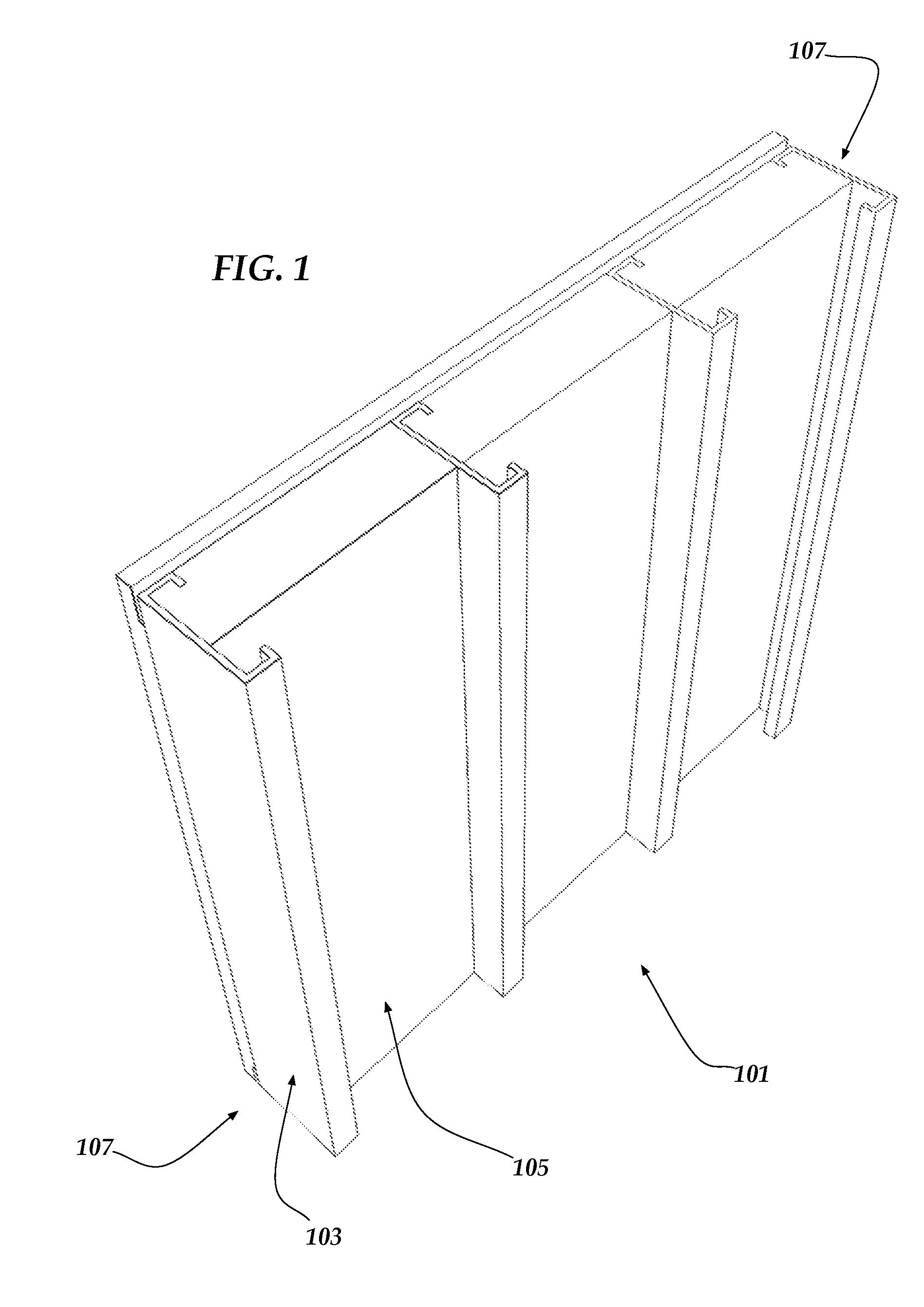
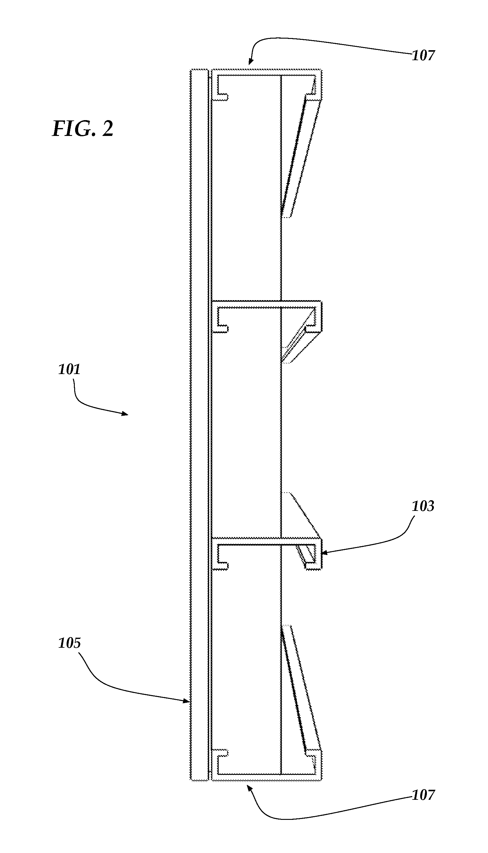
[0038]The instant invention is drawn to a rigid wall panel assembly for use in residential and commercial construction.

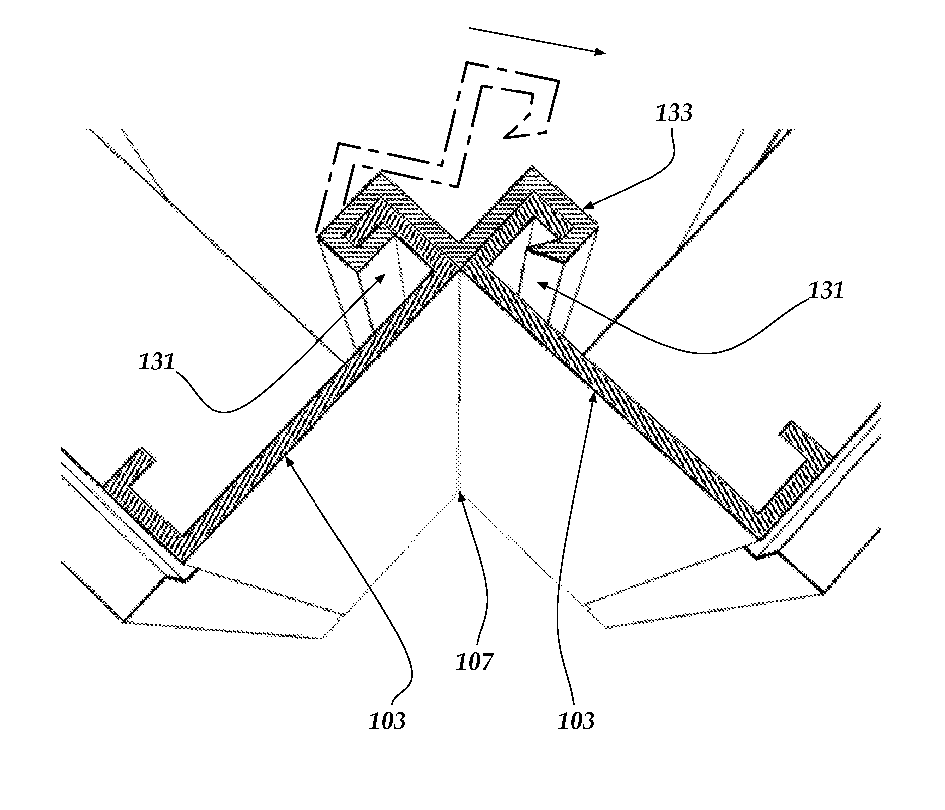
[0039]Referring to FIGS. 1 and 2, the rigid wall panel assembly 101 of the instant invention is formed by spacing apart a plurality of C-shaped studs 103, preferably metal, wherein a sufficient number of C-shaped studs 103 are used to provide the desired length for rigid wall panel assembly 101. While the dimensions of the C-shaped studs 103 can be varied greatly, it is preferable that each C-shaped stud 103 is approximately five and one-half (5½) inches in width. The spacing between C-shaped studs 103 will largely be determined by building codes and construction requirements for the location where rigid wall panel assembly 101 will be utilized. The C-shaped studs 103 are inserted into a foam block 105, preferably made of EPS foam, which allows C-shaped studs 103 to maintain the desired spacing. Each rigid wall panel assembly 101 has a C-shaped stud 103 at each long...


PUM

PropertyMeasurementUnit
Angleaaaaaaaaaa

Abstract

The invention is a prefabricated rigid wall panel assembly constructed of a plurality of C-shaped studs inserted into kerfs in a foam block. The closed ends of the C-shaped studs and the foam block form substantially planar longitudinal edges of the panel assembly capable of abutting an adjacent panel assembly. Optionally, a header and/or footer plate inserted is into a transverse kerf such that the plate overlaps the ends of the studs, and the header and/or footer plate and the foam block form a substantially planar transverse edge of the panel assembly. Adjacent panel assemblies are preferably secured to one another using a clip, the shape of which depends on the angle at which the panel assemblies abut. Each panel assembly may also have a wire chase.

Description

CROSS REFERENCES[0001]This application claims priority to U.S. Application Ser. No. 60 / 967,502, filed Sep. 5, 2007.GOVERNMENTAL RIGHTS[0002]None.BACKGROUND OF THE INVENTION[0003]This invention relates to a preformed rigid wall panel system that is durable and easy to manufacture, transport, and install on-site.[0004]Wall structures for buildings are generally manufactured on either a wooden or metal skeletal system of spaced-apart vertical studs bordered by a top plate and a bottom plate. Such wall structures have historically been built on-site with workers manually joining together the vertical studs and top and bottom plates, then raising the wall structure into place and securing it to the floor system of the building. A surface covering is then applied over the frame section, such as gypsum board, drywall, or plaster. Often, insulation is positioned between the vertical studs prior to installation of the surface covering.[0005]In recent years, manufacturers have begun preparing...

Claims


Application Information

Patent Timeline
IPC IPC(8): E04C1/00
CPCE04B1/14E04B1/6116E04C2/22E04C2/205E04B2001/6195
Inventor BARTON, STEVEN
Owner GREENSTEEL TECH
Why Eureka
Try Eureka