
Remotely operated brake tester and method of testing

a brake tester and remote operation technology, applied in the direction of instruments, measurement devices, force/torque/work measurement apparatus, etc., can solve the problems of time-consuming and laborious procedures, not enabling the driver to determine whether the brakes at each wheel are operating properly, and the cost of testing is high. , to achieve the effect of simple and inexpensive us

Inactive Publication Date: 2009-03-05
STEININGER JOSEPH
View PDF25 Cites 15 Cited by
  • Summary
  • Abstract
  • Description
  • Claims
  • Application Information

AI Technical Summary

Benefits of technology

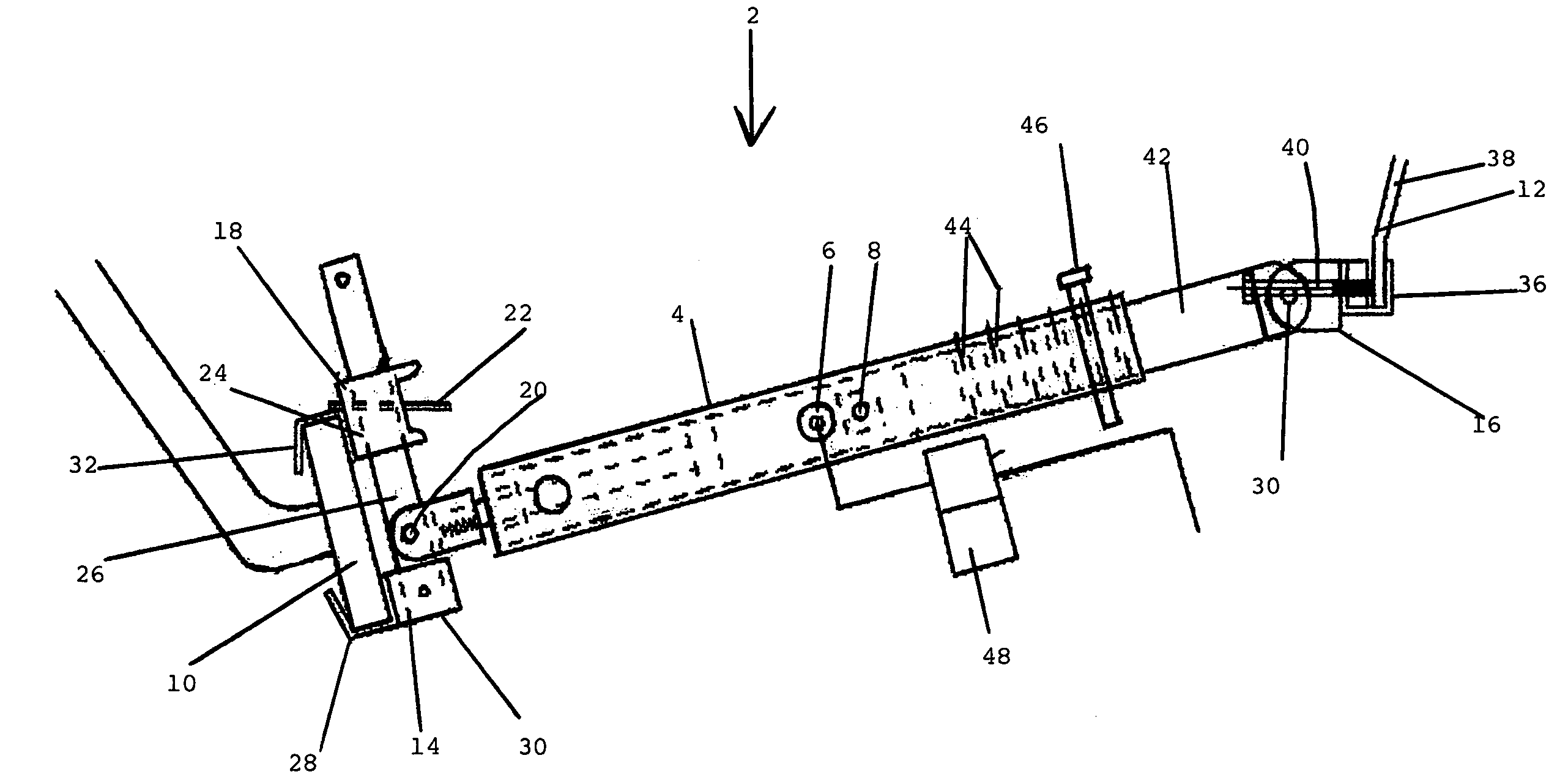
[0008]It is an object of the present invention to provide a brake tester that is relatively inexpensive and simple to use to test the brakes remotely at any time by one person acting alone by pressing and releasing the brake pedal remotely while observing the movement of each of the brakes in succession.

Problems solved by technology

Truck drivers are required to check the brakes of the truck they are driving and truck drivers and / or owners of trucks are often fined if the brakes of a truck are found not to be working properly when the brakes are inspected by government authorities.
This can be a time consuming procedure and requires two persons.
Such a test does not enable the driver to determine whether the brakes at each wheel are operating properly.
The device described in the Foster patent is expensive, complex and cumbersome and is not suitable for use in testing the brakes of a motor vehicle when the vehicle is enroute or when the trailer is attached to the tractor.

Method used


Image

  • Remotely operated brake tester and method of testing
  • Remotely operated brake tester and method of testing
  • Remotely operated brake tester and method of testing

Examples


Embodiment Construction

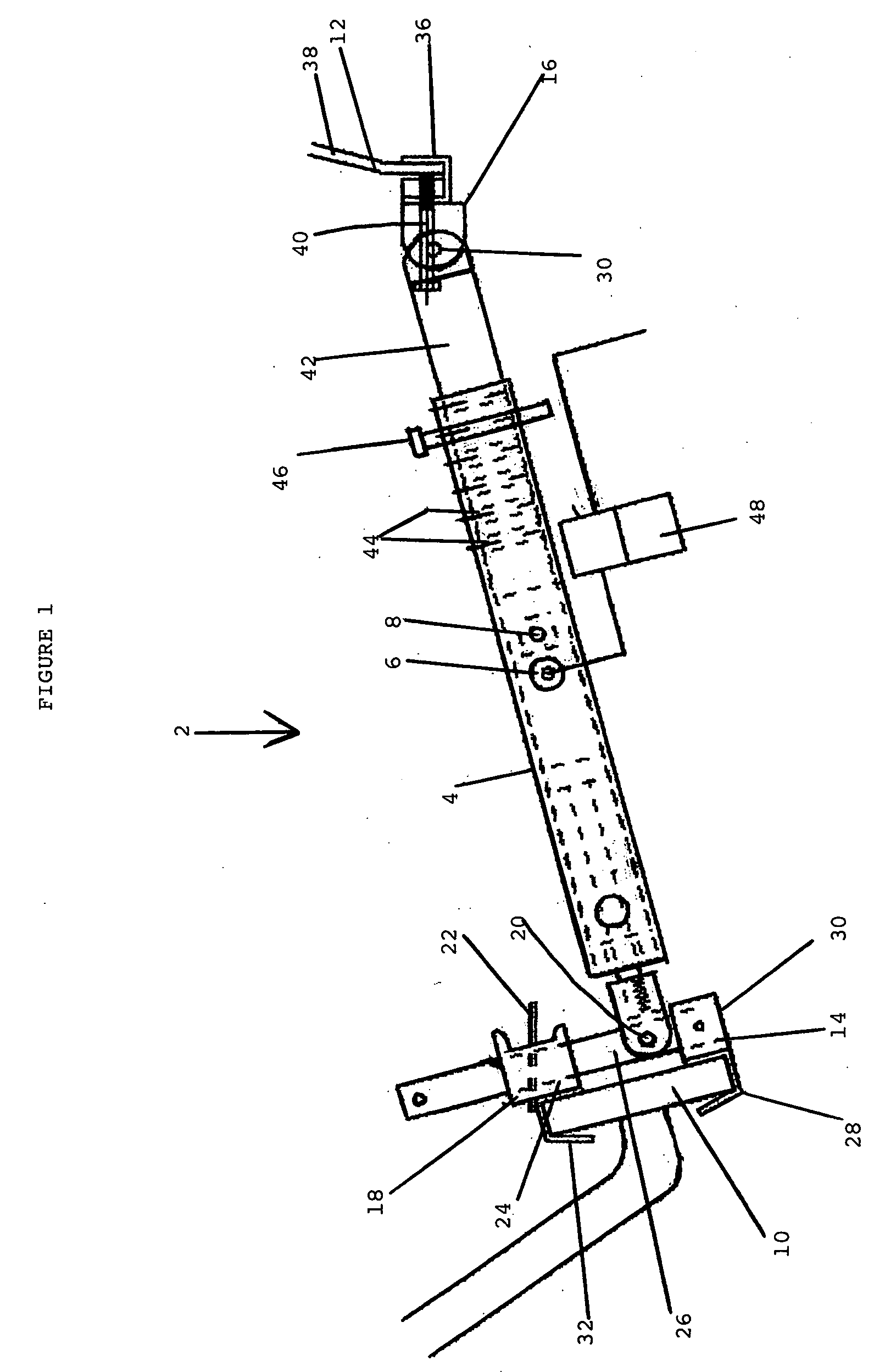
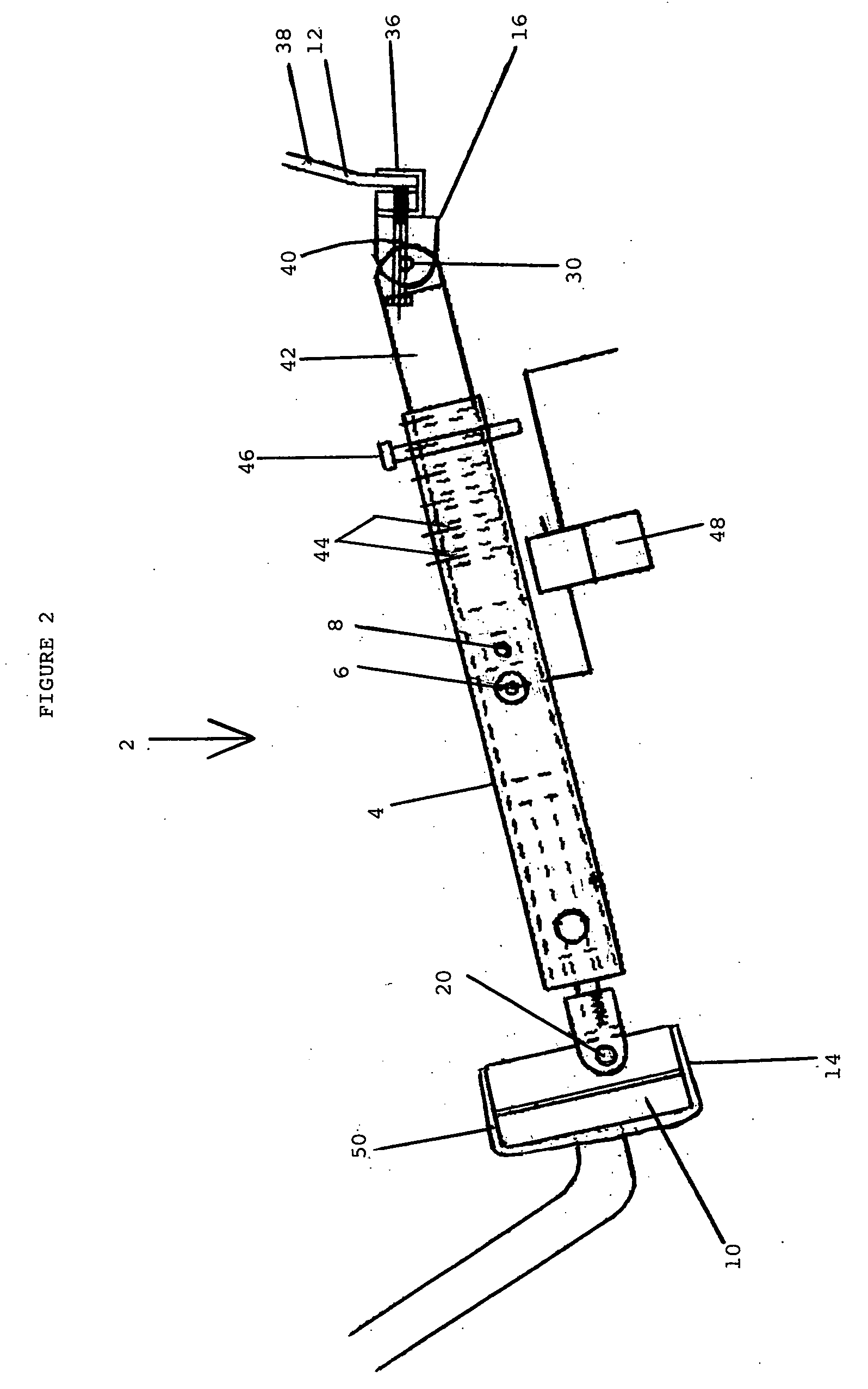
[0023]In FIG. 1, a brake tester 2 has an elongated member 4 with a switch 6 and an air inlet 8. The tester 2 is connected between a brake pedal 10 and a base 12. The base 12 can be located on an underside of the driver's seat or can be located at a front of the seat or even on a steering wheel of the vehicle (not shown). The tester has a first end 14 and a second end 16. The first end 14 is connected to an adjustable retainer 18 by a hinge 20. The retainer 18 is adjustable by a handle 22 that causes a bracket 24 to move along a post 26. The post 26 has a series of projections and indentations thereon so that the distance of the bracket along the post can be almost infinitely adjusted. A first arm 28 is connected to a fixed end 30 of the retainer 18 and the second arm 32 is affixed to the bracket 24.

[0024]The second end 16 has a hinge 34 connected to a retainer 36 which is connected to a seat bracket 38 by a bolt 40. The second end 16 has a bar 42 which has a series of openings 44 th...


PUM

PropertyMeasurementUnit
electrical poweraaaaaaaaaa
lengthaaaaaaaaaa
areaaaaaaaaaaa

Abstract

A brake tester and method testing brakes uses an elongated member that has an extended position and retracted position. The elongated member is installed between the brake pedal of a vehicle and a base and can be extended and retracted by a user from outside the vehicle using a remote. The tester is preferably used to test air brakes and is powered electronically and by air under pressure. The tester can be made to operate under electrical power alone, without pneumatic pressure.

Description

[0001]Applicant claims the benefit of U.S. Provisional Application Ser. No. 60 / 968,944 filed on Aug. 30, 2007.BACKGROUND OF THE INVENTION[0002]1. Field of the Invention[0003]This invention relates to a brake tester, a combination of brake pedal and motor vehicle and to a method of operation thereof for the brakes of a motor vehicle and, more particularly, relates to a tester and method of operation for air brakes.[0004]2. Description of the Prior Art[0005]Truck drivers are required to check the brakes of the truck they are driving and truck drivers and / or owners of trucks are often fined if the brakes of a truck are found not to be working properly when the brakes are inspected by government authorities. Truck inspection stations are located periodically along major highways. In addition to fines, the truck can be taken off the road by government authorities until such time as the brakes are repaired. It is therefore important that truck drivers check the operation of all of the bra...

Claims


Application Information

Patent Timeline
Patent Type & Authority Applications(United States)
IPC IPC(8): G01L5/28
CPCG01L5/28
Inventor STEININGER, JOSEPH
Owner STEININGER JOSEPH
Learn More