Roller mill for grinding solid material

a technology of solid materials and roller mills, which is applied in the direction of grain treatment, etc., can solve the problems of unsatisfactory removal of mill stands and profit, and achieve the effect of increasing the capacity of mills

Active Publication Date: 2009-03-05
F L SMIDTH & CO AS
View PDF2 Cites 7 Cited by
  • Summary
  • Abstract
  • Description
  • Claims
  • Application Information

AI Technical Summary

Benefits of technology

[0005]It is the object of the present invention to provide a roller mill with an increased number of rollers, in order to increase the capacity of the mill, without the above-mentioned drawbacks.

Problems solved by technology

Because of this, vertical mills are generally limited to a maximum of four permanent mill stands, one for each grinding roll assembly, as the space between the mill stands otherwise will be too narrow for replacement of the gear reducer.
While possible, it is not ideal to remove one of the mill stands in order to replace or repair the gear reducer.
The higher costs due to such an increase in component size counteract any profit gained due to the mill capacity increase realized by increasing the number of grinding rollers.

Method used


Image

  • Roller mill for grinding solid material
  • Roller mill for grinding solid material
  • Roller mill for grinding solid material

Examples


Embodiment Construction

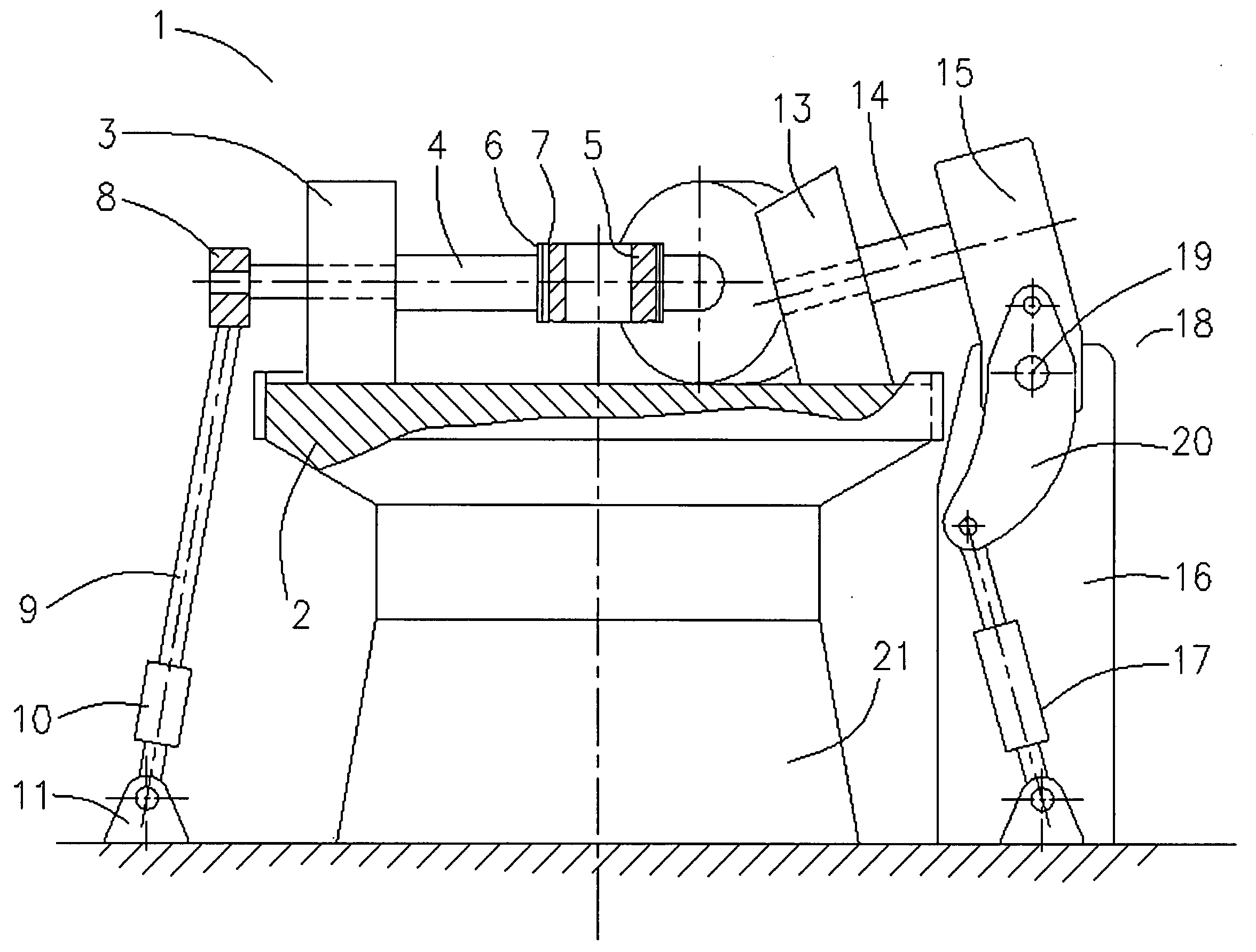
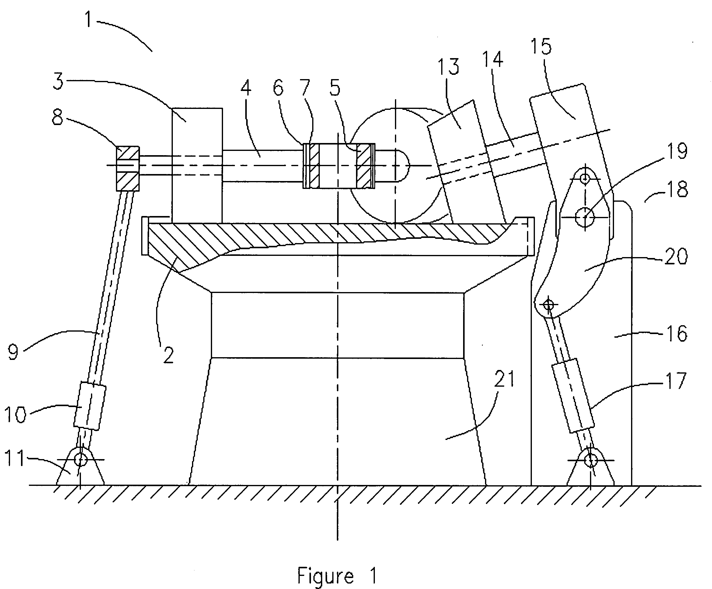
[0022]In FIG. 1 is seen a side view of a roller mill 1, which comprises a horizontal grinding table 2 rotating about a vertical axis and supported by a gear reducer 21. Rollers 3, 13 are configured to operate interactively with the grinding table 2. Roller 3 rotates about a stationary shaft 4 attached to a frame 5. The shafts 4 are attached to the frame 5 by means of flanges 6 on the shafts 4 and corresponding flanges 7 provided on the frame 5 and are located above and over table 2.

[0023]On the outer end of each shaft 4 is mounted a bracket 8 to which a draw bar 9 pivotally is attached, whereby the roller 3 can be forced against the grinding table 2 by means of a hydraulic cylinder 10 pivotally retained in a bracket 11, which is anchored in the mill foundation.

[0024]With reference to conventionally mounted roller 13, a rocker arm assembly 18 is pivotally mounted to a mill stand 16. Roller 13 is mounted on a shaft 14, which is fixed to an end of a rocker arm 15, for rotation about th...


PUM


Abstract

The invention relates to a roller mill for grinding solid material such as cement raw materials and similar materials, said roller mill comprising a substantially horizontal grinding table and at least two rollers which are configured for interactive operation with said grinding table. wherein at least one of said rollers rotates about a stationary shaft connected to a rocker arm pivotally connected to a mill stand which substantially is situated outside said grinding table and therefore does not utilize a mill stand and the remaining rollers do not utilize a mill stand. According to the invention the number of rollers, and thereby the capacity of the mill is increased without introducing more mill stands.

Description

FIELD OF INVENTION[0001]A roller mill for grinding solid material such as cement raw materials and similar materials, the roller mill comprising a horizontal grinding table and at least two grinding rollers, which are configured for interactive operation with the grinding table.BACKGROUND OF THE INVENTION[0002]A roller mill of the aforementioned kind is known for example from U.S. Pat. No. 4,828,189. This known mill is a so-called vertical mill and comprises a casing or mill body with a horizontal grinding table positioned within the mill body mounted for rotation about a vertical axis. Drive means such as a motor and a gear reducer, situated beneath the grinding table, are provided for rotating the grinding table. Rocker arms are mounted in the roller mill structure and in the end of each rocker arm a grinding roller is mounted for rotation about an axis, which is situated at a predetermined angle to the table. The load-carrying mill structure is assembled from a plurality of mill ...

Claims


Application Information

Patent Timeline
Patent Type & Authority Applications(United States)
IPC IPC(8): B02C15/00
CPCB02C15/04B02C15/004B02C15/14
Inventor EUCULANO, JASON S.
Owner F L SMIDTH & CO AS
Why Eureka
Try Eureka