Nondestructive inspection method and device

Inactive Publication Date: 2009-03-05
NAT UNIV CORP KYUSHU INST OF TECH (JP)
View PDF0 Cites 0 Cited by
  • Summary
  • Abstract
  • Description
  • Claims
  • Application Information

AI Technical Summary

Benefits of technology

[0010]According to the present invention, reinforcing bars, etc. in a structure can be readily and nondestructively inspected, and corroded reinforcing bars can be efficiently evaluated. Therefore, the present invention facilitates inspection of reinforcing bars, etc. in a structure in the field of civil engineering and construction (construction industry), and thus enables the period of maintenance of a structure (e.g., a tunnel, a bridge, or a building) to be estimated. According to the present invention, even when pipes are thickly covered with a heat-insulating material or a protective material, corrosion of the pipes can be inspected without removal of the heat-insulating material or protective material. In addition, pipes, etc. in the ground can be inspected without digging up the ground.

Problems solved by technology

However, currently, no convenient technique is available for nondestructively determining or evaluating the corrosion state of reinforcing bars in the interior of a concrete structure, and such determination or evaluation requires a long period of time and high cost.
However, these apparatuses do not actively utilize magnetization.

Method used


Image

  • Nondestructive inspection method and device
  • Nondestructive inspection method and device
  • Nondestructive inspection method and device

Examples


example 1

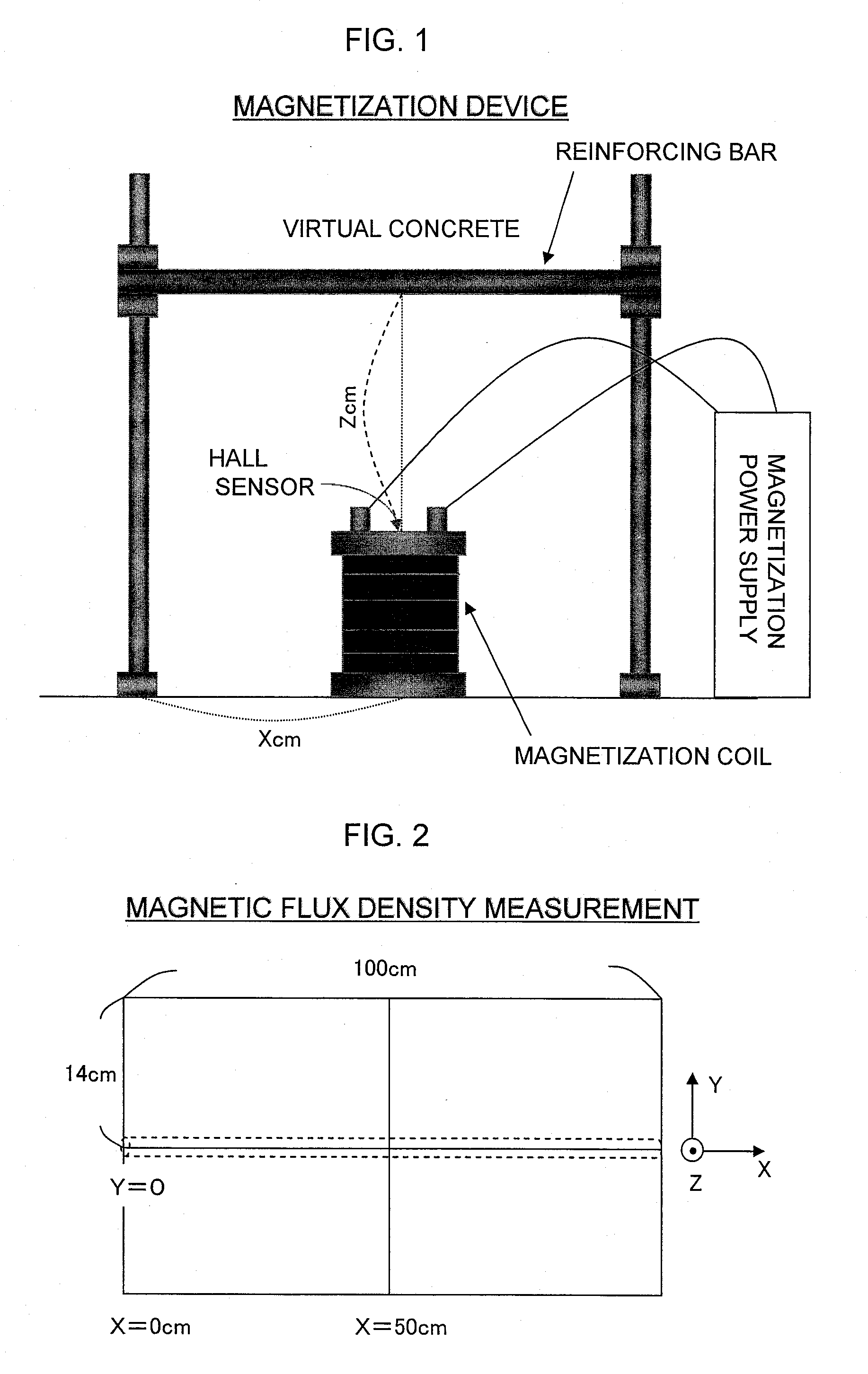
[0041]An example of a magnetization power supply which may be employed in the present invention can supply a direct pulse electric current (up to 20,000 A) for magnetization. In addition, the magnetization power supply can supply an alternating current (up to 7,000 A) for demagnetizing a once-magnetized reinforcing bar so that the current is gradually reduced.

[0042]A magnetic field generated varies depending on the size of a magnetization coil employed or the number of coil turns. An example of a magnetization coil (hollow core) which may be employed in the present invention has the following specification.

[0043]Inner diameter: 30 mm, outer diameter: 118 mm, height: mm, wire diameter: 1.5 mm, number of turns: 690, coil resistance: 1.20Ω (at ambient temperature), 0.5Ω (in liquid nitrogen), and bobbin material: stainless steel.

example 2

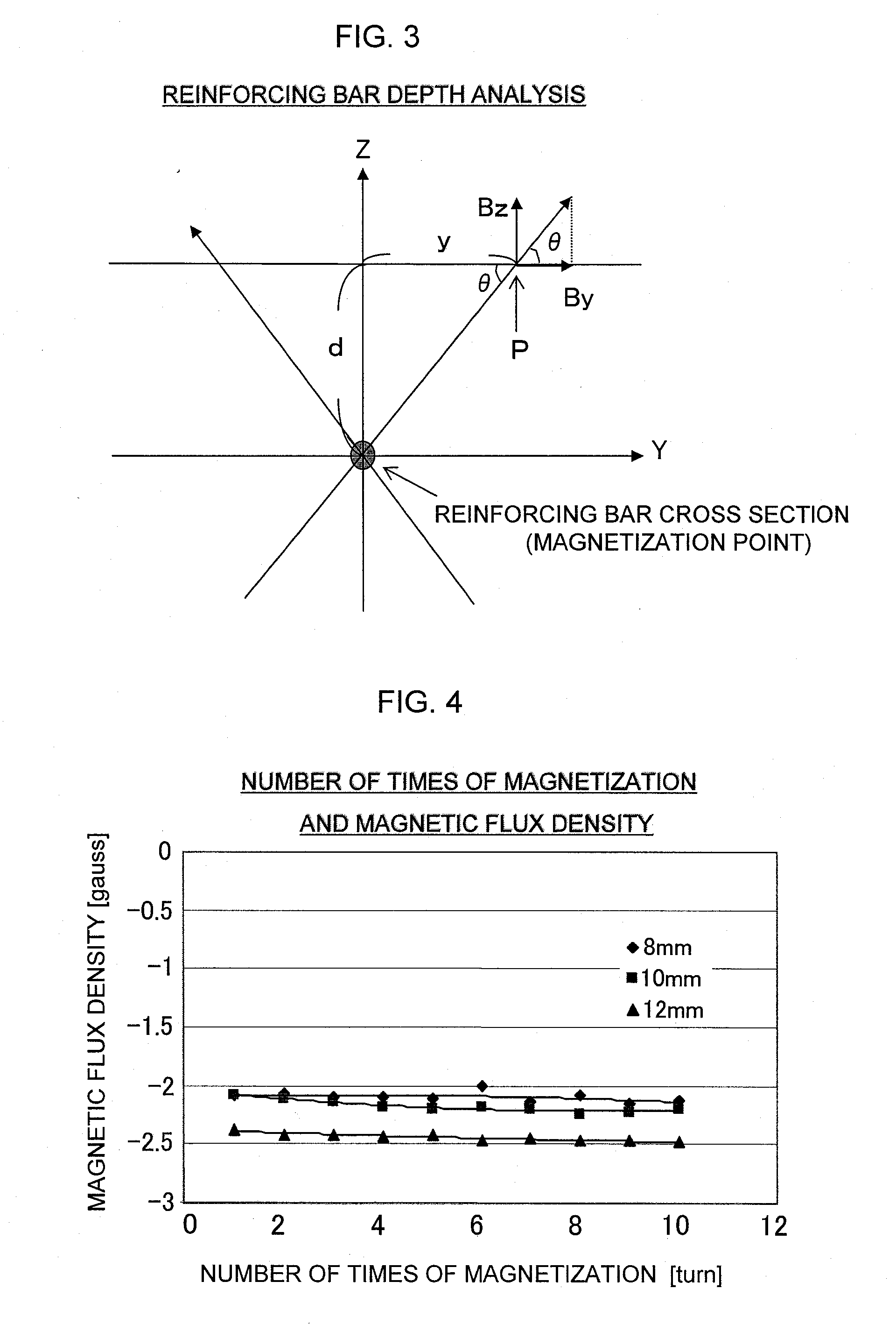
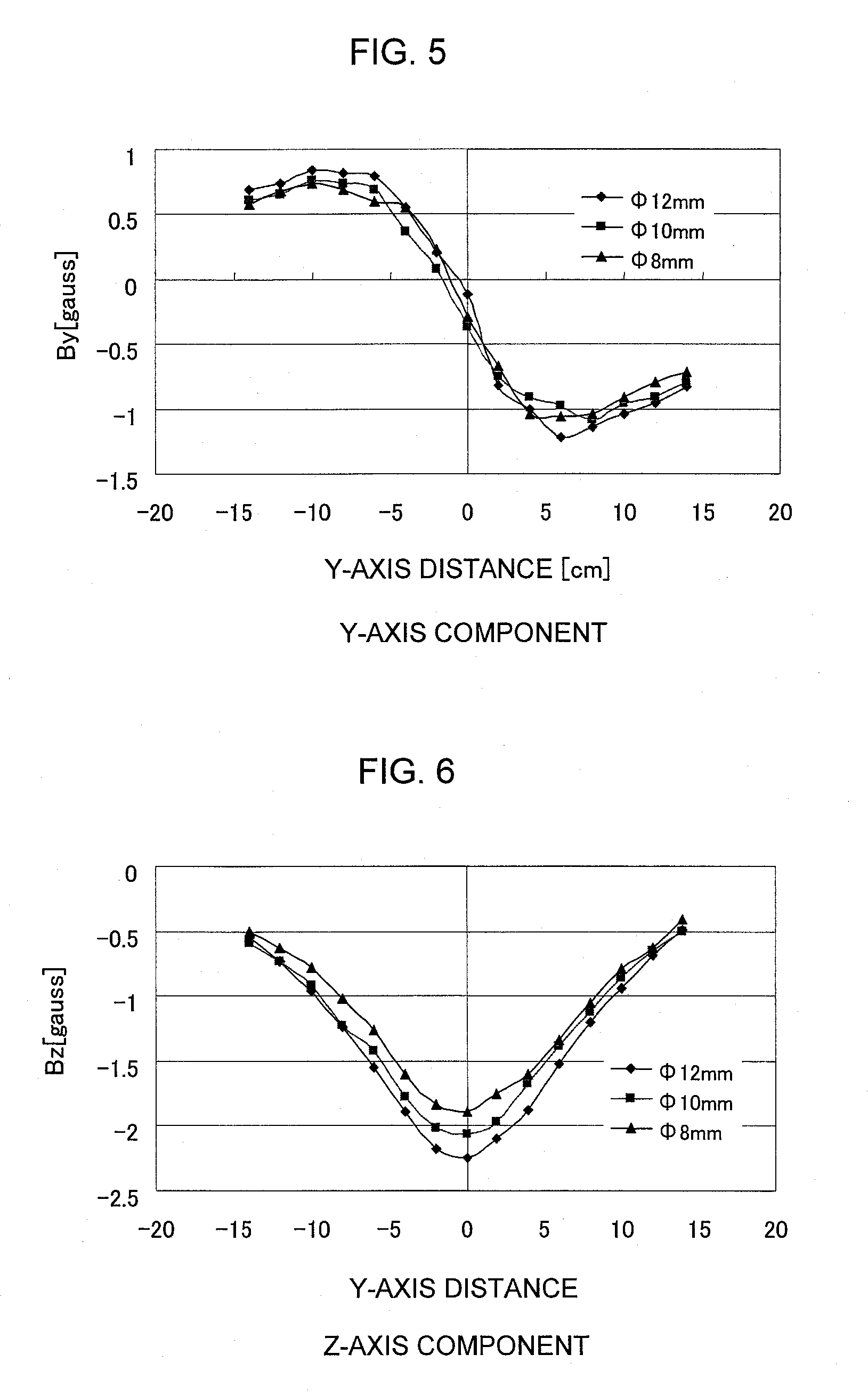
[0044]FIGS. 5 and 6 are graphs respectively showing results of measurement of a Y-axis magnetic flux component By and a Z-axis magnetic flux component Bz performed for three different reinforcing bars having diameters of 8, 10, and 12 mm (reinforcing bar depth: 10 cm each) while changing the Y-axis distance. On the basis of these measurement data, reinforcing bar depth d can be determined by use of the formula: d=(Bz / By)·y as described above with reference to FIG. 3.

[0045]FIG. 7 is a graph showing data of determined reinforcing bar depth d. As is clear from FIG. 7, the reinforcing bar depth is almost exactly determined to be 10 cm through magnetic flux measurement (exclusive of a region in the vicinity of a Y-axis value of zero).

example 3

[0046]FIG. 8 is a graph showing data of maximum magnetic flux density as measured on three different reinforcing bars having diameters of 8, 10, and 12 mm under varied reinforcing bar depths. Maximum magnetic flux density is obtained as a Z-axis magnetic flux component (Bz) at a point in a direction perpendicular to the magnetization point (i.e., in the Z-axis direction) (see FIG. 3). In other words, the maximum magnetic flux density is obtained when the magnetic flux which emanates radially from the reinforcing bar is detected as a radial-direction magnetic flux component at a point that is located outside a concrete structure and is closest to the magnetization point of the reinforcing bar. As is clear from FIG. 8, when reinforcing bar depth is small, a large difference in maximum magnetic flux density is observed between reinforcing bars of different diameters. However, the greater the reinforcing bar depth, the smaller the difference in maximum magnetic flux density. Conceivably...


PUM


Abstract

The present invention nondestructively analyzes the position or corrosion state of a magnetic material present in the interior of a non-magnetic material structure. The magnetic material is magnetized from the outside of the structure, and magnetic flux density of the thus-magnetized magnetic material is measured at the outside of the structure, to thereby specify the position of the magnetic material or to analyze the corrosion state of the magnetic material. The magnetic material is magnetized in two stages. After the position of the magnetic material magnetized through first-stage magnetization is specified through measurement of magnetic flux density of the magnetic material, the magnetic material is demagnetized through application of an alternating magnetic field. After second-stage magnetization is performed at a position facing the thus-specified magnetic material position, magnetic flux density of the thus-magnetized magnetic material is measured, to thereby analyze the corrosion state of the magnetic material.

Description

TECHNICAL FIELD[0001]The present invention relates to a nondestructive inspection method and apparatus for nondestructively analyzing the position or corrosion state of a magnetic material (e.g., reinforcing bar or pipe) present in the interior of a structure made of a non-magnetic material (e.g., concrete, heat-insulating material, or protective material).BACKGROUND ART[0002]In the field of civil engineering and construction (construction industry), a very important point for the maintenance of a concrete structure (e.g., a tunnel, a bridge, or a building) is to understand the position of corroded reinforcing bars in the concrete structure or the degree of corrosion of the reinforcing bars. However, currently, no convenient technique is available for nondestructively determining or evaluating the corrosion state of reinforcing bars in the interior of a concrete structure, and such determination or evaluation requires a long period of time and high cost.[0003]There have been known a...

Claims


Application Information

Patent Timeline
IPC IPC(8): G01R33/12
CPCG01N17/00G01N33/383G01N27/90
Inventor KOMORI, MOCHIMITSU
Owner NAT UNIV CORP KYUSHU INST OF TECH (JP)
Why Eureka
Try Eureka