Method for evaluating collision performance of vehicle member, and member collision test device used for same

Active Publication Date: 2012-05-31
NIPPON STEEL CORP
View PDF8 Cites 17 Cited by
  • Summary
  • Abstract
  • Description
  • Claims
  • Application Information

AI Technical Summary

Benefits of technology

[0019]In the collision performance evaluating method of the above aspect (1), the boundary condition of the partial structure CAE model is determined so that the difference between the collision performance evaluation parameter in the partial structure CAE model and the collision performance evaluation parameter in the full vehicle CAE model is in a predetermined range. By this process, even in the partial structure CAE model, as for the full vehicle CAE model, it is possible to precisely reflect the influence applied from peripheral members during a collision, and therefore the collision performance of the memb

Problems solved by technology

However, in a case where any member has insufficient strength, measures are taken to increase the strength of the member, and then a prototype vehicle needs to be build again to perform a collision test again.
This process needs much development cost and time, which has a great influence on the development process.
However, in a case where 3-point bending test or the like is performed on each of those members separately, compared with the case a collision test is performed in a state where those members are mounted in an actual vehicle body, the support method of the member and the influence exerted by peripheral members may not be sufficiently reflected, and therefore the evaluation accuracy is too low to determine whether or not to adopt the member for an actual vehicle.
However, the collision simulation in the full vehicle state is a ver

Method used


Image

  • Method for evaluating collision performance of vehicle member, and member collision test device used for same
  • Method for evaluating collision performance of vehicle member, and member collision test device used for same
  • Method for evaluating collision performance of vehicle member, and member collision test device used for same

Examples


Example

EXAMPLE

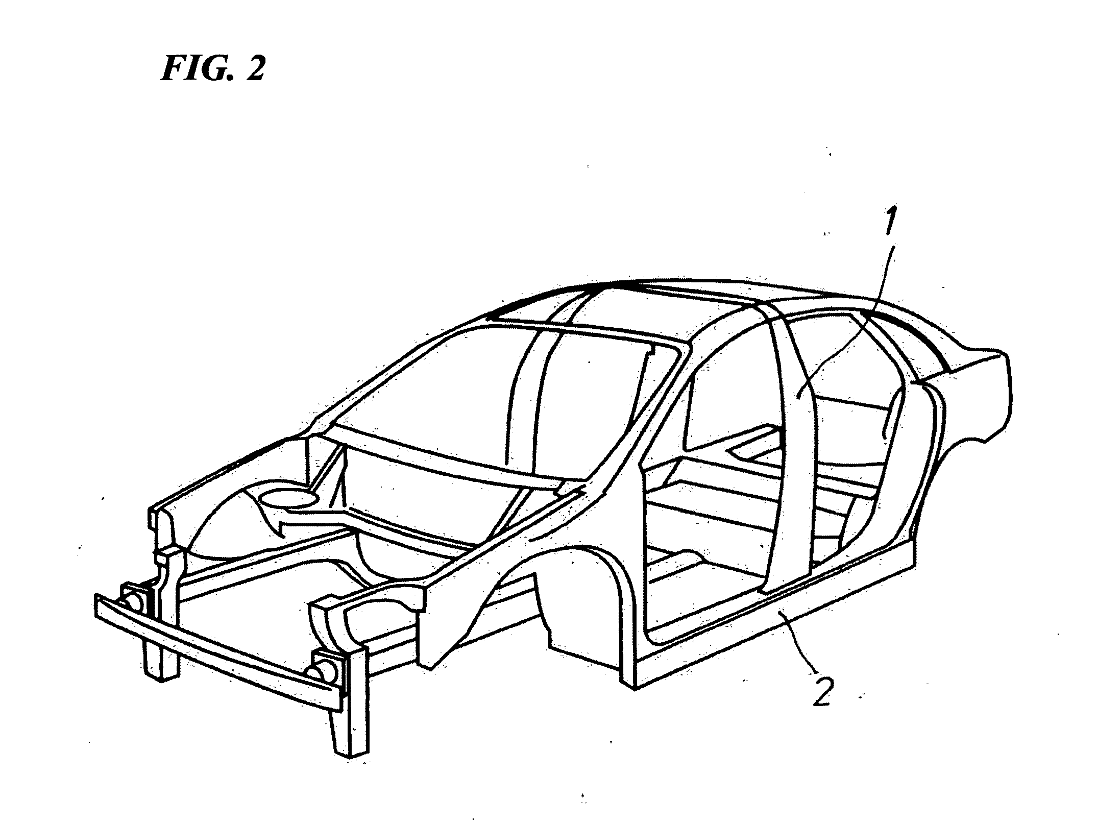
[0050]Hereinafter, an example of the method according to an embodiment of the present invention will be described. In this example, the deformation of the center pillar 1 and the side sill 2 in a side collision was analyzed. A partial structure CAE model suitable to the analysis was build and adjusted, and the simulation of the member collision test and the member collision test device as a physical equipment were performed.

[0051]As the full vehicle information, the result of an existing full vehicle CAE simulation was acquired to analyze deformation characteristics of the center pillar 1 and the side sill 2 during a collision. As indexes of the deformation characteristics of the center pillar 1 used for determining a boundary condition, a maximum deformation amount L along the colliding direction of the center pillar and a profile of the entire center pillar deformed were used. The profiles of the center pillar before and after the full vehicle collision test are shown in F...


PUM


Abstract

A performance evaluation method of a vehicle member includes a calculation process for performing an analysis using a partial structure CAE model modeling a module where a member of a vehicle to be evaluated and a collision test device for conducting a collision test on the member are combined, and obtaining a value of a collision performance evaluation parameter in the partial structure CAE model; a calculation process for determining a boundary condition of the partial structure CAE model; a calculation process for determining a test condition of a member collision test device based on the boundary condition of the partial structure CAE model; and a test process for conducting a collision test using a physical member collision test device and a physical member, based on the set condition of the member collision test device.

Description

TECHNICAL FIELD[0001]The present invention relates to a collision performance evaluation method of a vehicle member performed in a vehicle development and design stage, and a member collision test device used for the same.[0002]Priority is claimed on Japanese Patent Application No. 2009-181208, filed Aug. 4, 2009, the content of which is incorporated herein by reference.BACKGROUND ART[0003]In the vehicle development and design stage, the evaluation of collision performance of a vehicle body is inevitable, and a vehicle maker builds a prototype vehicle and performs a collision test (collision experiment) to check that collision performance is ensured as desired and then proceeds to mass production. However, in a case where any member has insufficient strength, measures are taken to increase the strength of the member, and then a prototype vehicle needs to be build again to perform a collision test again. This process needs much development cost and time, which has a great influence o...

Claims


Application Information

Patent Timeline
IPC IPC(8): G06F17/50G01N3/30
CPCG01M17/0078G01M7/08G01M17/00
Inventor ITO, YASUNORIKAWANO, KAZUYUKITANAKA, YASUHARUYOSHIDA, HIROSHIKANDA, TOSHIYUKIHIROSE, SATOSHI
Owner NIPPON STEEL CORP
Why Eureka
Try Eureka