Test structure for opc-related shorts between lines in a semiconductor device

Active Publication Date: 2008-05-01
ADVANCED MICRO DEVICES INC
View PDF38 Cites 6 Cited by
  • Summary
  • Abstract
  • Description
  • Claims
  • Application Information

AI Technical Summary

Benefits of technology

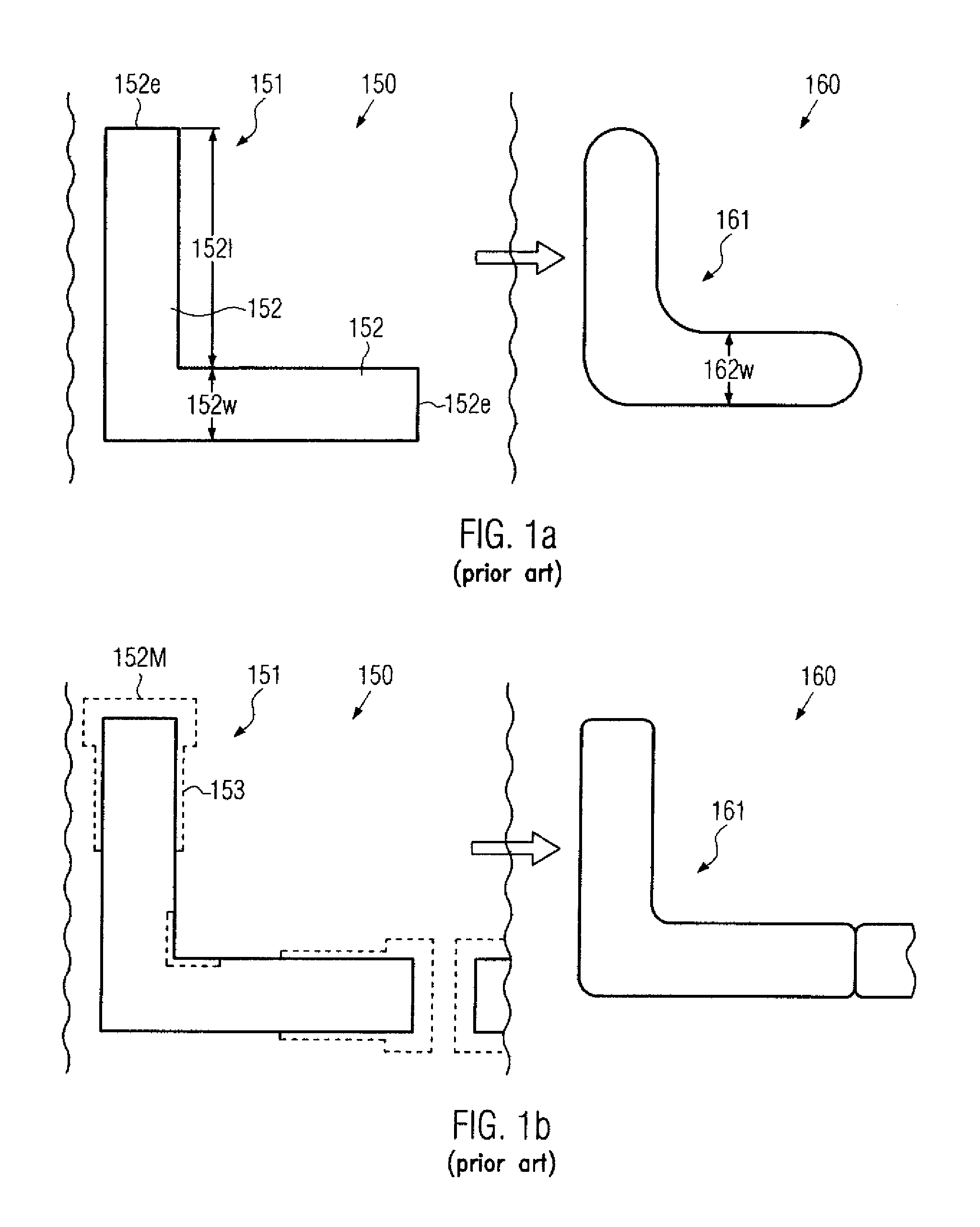
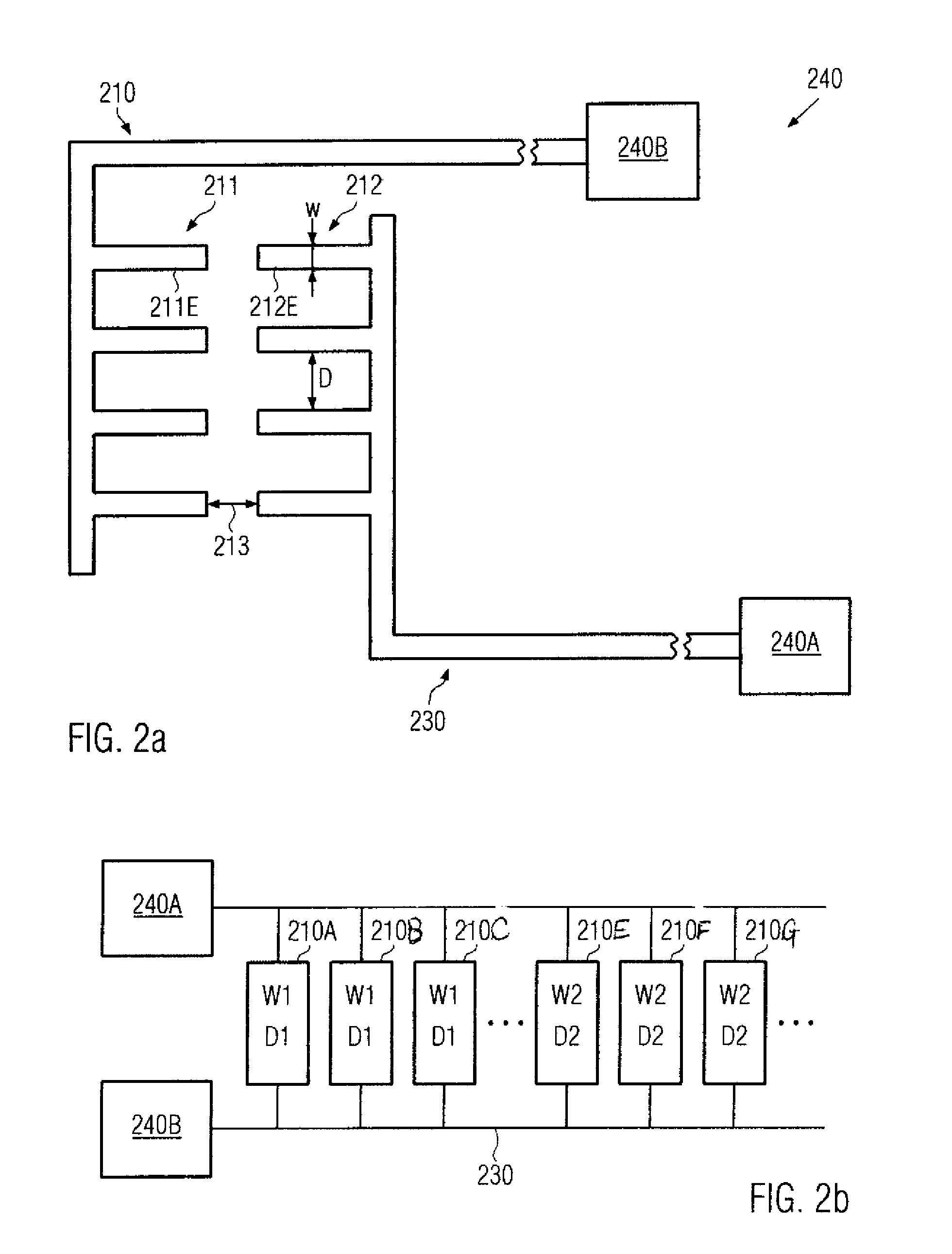
[0014]Generally, the subject matter disclosed herein relates to a technique for determining the characteristics of OPC-related influences on the lithography process for forming specific structures, such as metallization structures, of semiconductor devices by assessing respective test assemblies or patterns in view of leakage current. For this purpose, a plurality of test patterns having different values with respect to OPC critical design parameters may be electrically coupled to obtain an electric output signal that may be used for evaluating the imaging process including the OPC correction mechanism. As previously explained, respective end portions of line features, such as metal lines, gate electrodes and the like, are subject to significant OPC corrections in order to reduce line end pull back caused by highly non-linear imaging processes. Thus, by monitoring the respective line features for a plurality of different conditions, which may be represented by varying parameter values for critical design parameters, on the basis of electrical test procedures, a highly efficient evaluation of the OPC model used in redesigning respective masks and reticles may be accomplished.

Problems solved by technology

For example, in critical lithography steps, an exposure wavelength of 193 nm may be used, which therefore may require complex techniques for finally obtaining resist features having dimensions well below the exposure wavelength.
However, the increased non-linearity may result in significant distortions of the resulting device features compared to the original features provided on the reticle.
Lithography processes with low linearity generally suffer, among others, from large line-end pullback, significant corner rounding, a strong dependence between feature area and printed CD (critical dimension), large CD vs. pitch variations.
In many cases, however, the corrections provided by the OPC tool may themselves result in non-desired modifications of the finally obtained device features.
However, due to limitations of the OPC model, such as restricted design databases, computational resources or other process conditions that may not be precisely incorporated into the respective model, the corrections may locally provide faulty device features.
For instance, the modified end portions 152M may result in a corresponding short between opposing line end portions, which cause severe performance degradations or even a complete failure of the device under consideration.

Method used


Image

  • Test structure for opc-related shorts between lines in a semiconductor device
  • Test structure for opc-related shorts between lines in a semiconductor device
  • Test structure for opc-related shorts between lines in a semiconductor device

Examples


Embodiment Construction

[0027]Various illustrative embodiments of the invention are described below. In the interest of clarity, not all features of an actual implementation are described in this specification. It will of course be appreciated that in the development of any such actual embodiment, numerous implementation-specific decisions must be made to achieve the developers' specific goals, such as compliance with system-related and business-related constraints, which will vary from one implementation to another. Moreover, it will be appreciated that such a development effort might be complex and time-consuming, but would nevertheless be a routine undertaking for those of ordinary skill in the art having the benefit of this disclosure.

[0028]The present subject matter will now be described with reference to the attached figures. Various structures, systems and devices are schematically depicted in the drawings for purposes of explanation only and so as to not obscure the present disclosure with details ...


PUM


Abstract

OPC results may be efficiently evaluated on the basis of a test structure containing a plurality of line features with opposing end portions. Thus, for different line parameters, the effect of OPC may be determined for a given critical tip-to-tip distance by determining the leakage behavior of the test assemblies, each having different design parameter values for line width and lateral distance between adjacent lines.

Description

BACKGROUND OF THE INVENTION[0001]1. Field of the Invention[0002]Generally, the present disclosure relates to the field of fabrication of integrated circuits, and, more particularly, to semiconductor devices having conductive lines, such as gate electrodes of field effect transistors, metal lines in the wiring levels of a semiconductor device, which are formed on the basis of advanced photolithography techniques.[0003]2. Description of the Related Art[0004]The fabrication of microstructures, such as integrated circuits, requires tiny regions of precisely controlled size to be formed in a material layer of an appropriate substrate, such as a silicon substrate, a silicon-on-insulator (SOI) substrate, or other suitable carrier materials. These tiny regions of precisely controlled size are generated by patterning the material layer by performing lithography, etch, implantation, deposition processes and the like, wherein typically, at least in a certain stage of the patterning process, a ...

Claims


Application Information

Patent Timeline
IPC IPC(8): H01L21/66H01L23/58
CPCH01L22/34H01L2924/0002H01L2924/00
Inventor FEUSTEL, FRANKWERNER, THOMASFROHBERG, KAI
Owner ADVANCED MICRO DEVICES INC
Why Eureka
Try Eureka