Circuit for sample rate conversion

a sample rate and circuit technology, applied in the field of digital integer factor sample rate conversion, can solve the problem that h(ktsub>f/sub>) symmetry generally does not yield intra-phase (anti)-symmetry

Active Publication Date: 2009-03-05
KEYSIGHT TECH
View PDF11 Cites 2 Cited by
  • Summary
  • Abstract
  • Description
  • Claims
  • Application Information

AI Technical Summary

Problems solved by technology

However, the h(kTf) (anti-)symmetry generally does not y

Method used


Image

  • Circuit for sample rate conversion
  • Circuit for sample rate conversion
  • Circuit for sample rate conversion

Examples


Embodiment Construction

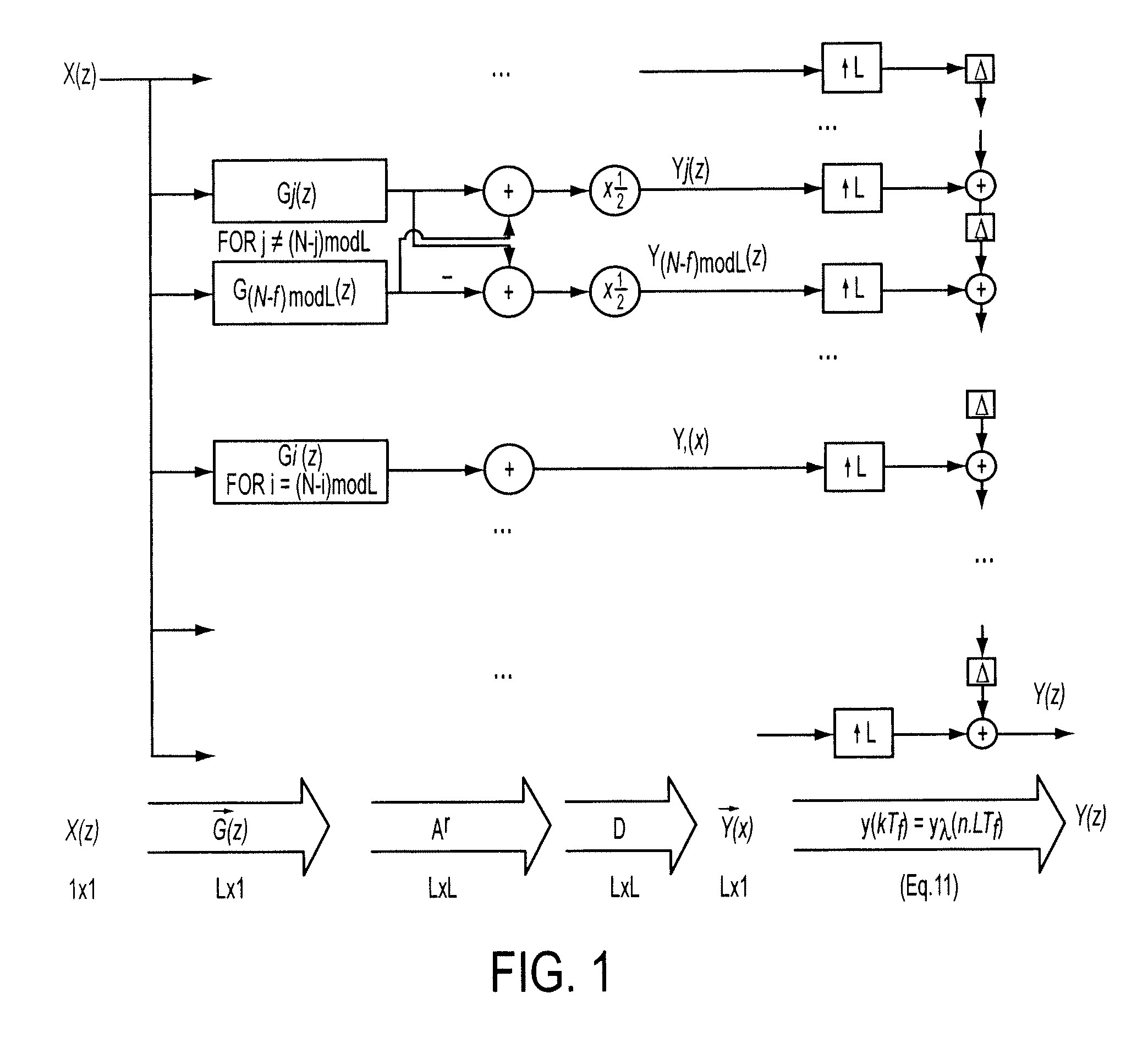
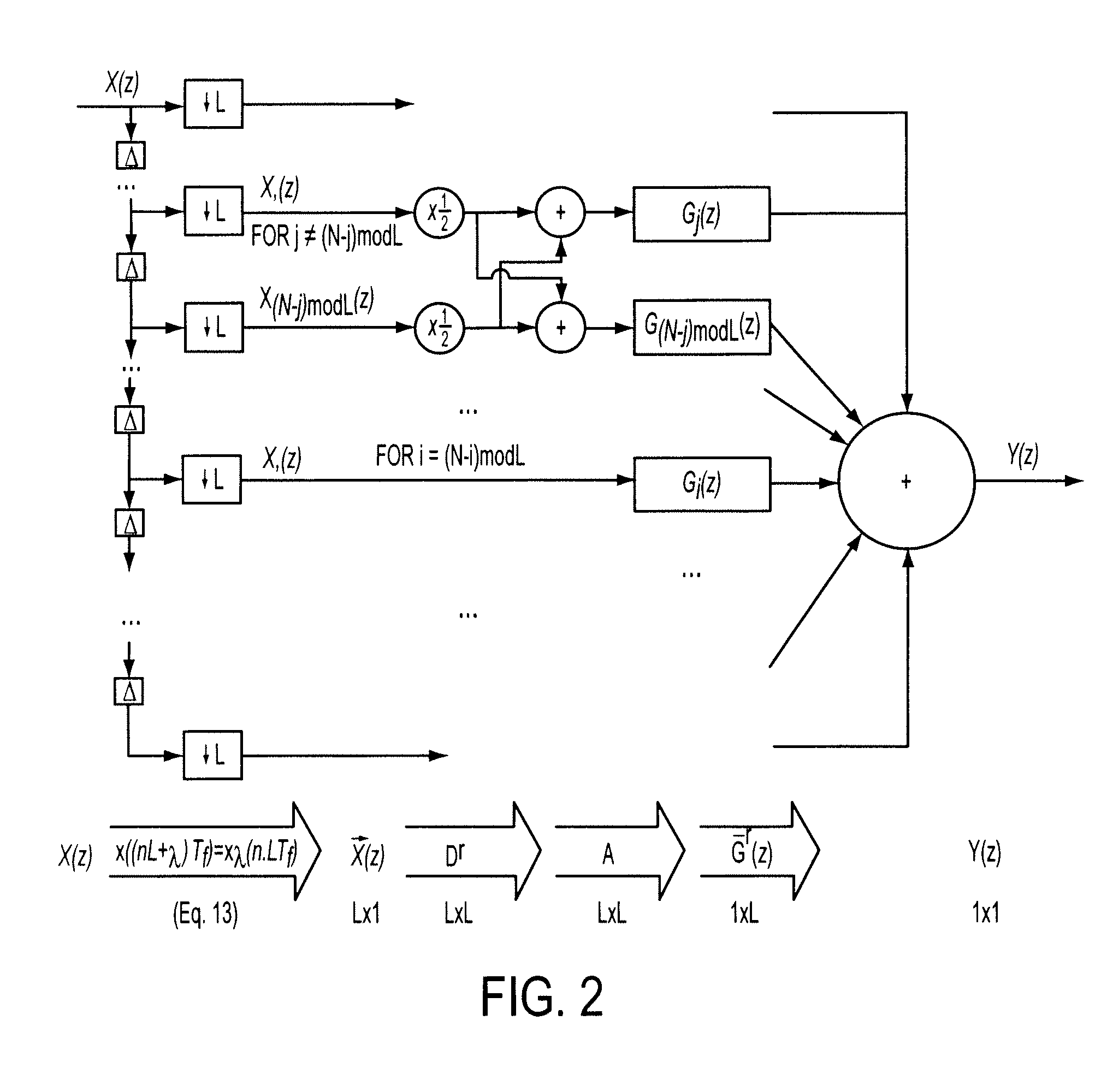
[0020]In the description of the invention below a Finite Impulse Response (FIR) with a symmetrical impulse response h(k) of length N+1 is assumed. Derivations for anti-symmetrical finite impulse response filters are similar and can readily be performed by a person skilled in the art. The filter is used as anti-imaging or anti-aliasing filter for L-factor interpolation or decimation, respectively.

[0021]The present invention aims at exploiting the h(k) symmetry and so to reduce the number of multiplications in a polyphase implementation, i.e. further than the factor L reduction in Equation 14.

[0022]The reduction is based on the fact that for each Hλ(z) that is not symmetrical by itself (“intra” symmetrical), a polyphase component with the “flipped” response exists. Define two transfer functions of order P, A(z) and B(z), as complementary if equation 17 is true. A(z) then is a “flipped” version of B(z), and vice versa.

A(z)=z−PB(z−1)  (Eq. 17)

First it is shown that each polyphase compon...


PUM


Abstract

The present invention is related to a circuit for converting the sample rate of a digital signal, comprising
    • an input for applying the digital signal,
    • a conversion filter having either a symmetrical or anti-symmetrical impulse response and implemented as a plurality of subfilters in parallel, each subfilter having a symmetrical or anti-symmetrical response derived from components of a polyphase decomposition of said impulse response,
    • combining means for deriving from said applied digital signal input signals of said plurality of subfilters or for combining output signals of said plurality of subfilters into a digital signal with converted sample rate,
    • an output for outputting said digital signal with converted sample rate.

Description

FIELD OF THE INVENTION[0001]The present invention relates to the field of digital integer factor sample rate conversion (i.e. decimation and interpolation).STATE OF THE ART[0002]Digital sample rate conversion (SRC) is a technique to replace a system that includes a variety of master clock rates with a fixed clock rate system. Applications are abundant, e.g. acquisition (signal generator) systems with an oversampled ADC (DAC), followed (preceded) by a digital decimator (interpolator) to relieve the analog anti-aliasing (reconstruction) filter specifications. Integer factor SRC also appears in analysis (i.e. decimation) and synthesis (i.e. interpolation) filter banks.[0003]To explain the problem tackled in the present invention a linear phase digital filter is assumed of order N, implying a finite impulse response h(k) of length N+1 (Eq. 1) with symmetric (Eq. 2) or anti-symmetric (Eq. 3) impulse response.y[n]=∑k=0Nh[k]x[n-k](Eq.1)h[k]=h[N-k]withk∈0…N(Eq.2)h[k]=-h[N-k]withk∈0…N(Eq.3)T...

Claims


Application Information

Patent Timeline
IPC IPC(8): H03M7/00
CPCH03H17/0223H03H17/0664H03H17/0657H03H17/0275H03H17/0621
Inventor VAN DE SANDE, FRANKANDRIES, ALVIN
Owner KEYSIGHT TECH
Why Eureka
Try Eureka