Method of transmitting data in multiple antenna system

a multi-antenna system and data technology, applied in the field of wireless communication, can solve problems such as difficulties in scheduling radio resources, errors in uplink control signals transmitted from user equipment,

Active Publication Date: 2009-03-05
LG ELECTRONICS INC
View PDF11 Cites 164 Cited by
  • Summary
  • Abstract
  • Description
  • Claims
  • Application Information

AI Technical Summary

Benefits of technology

[0012]The present invention provides a method for scheduling and transmitting data, which can cope with errors that may occur in uplink control signals needed for scheduling radio resources.

Problems solved by technology

Errors may occur in uplink control signals transmitted from the user equipment to the base station in the process of transmission.
If an error occurs in an uplink control signal, it may cause difficulties to schedule radio resources.
However, it is not clearly suggested how to make up for an error when the error occurs in the uplink control signal that is needed by the base station for scheduling radio resources.

Method used


Image

  • Method of transmitting data in multiple antenna system
  • Method of transmitting data in multiple antenna system
  • Method of transmitting data in multiple antenna system

Examples


Embodiment Construction

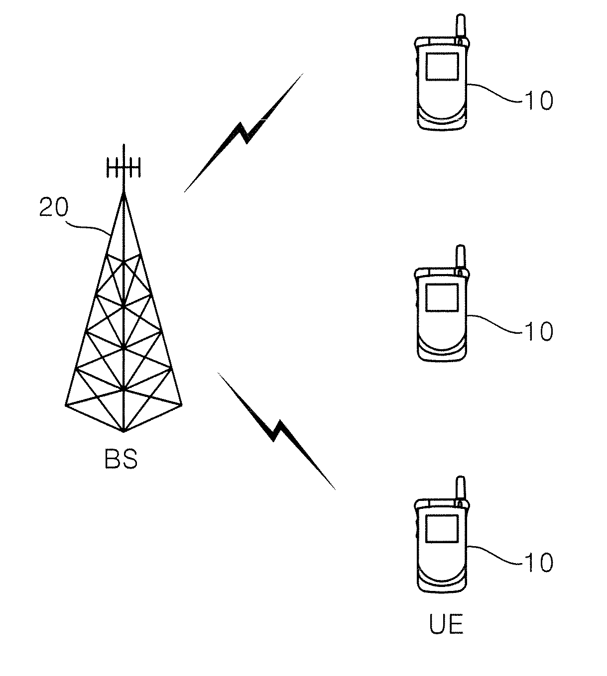
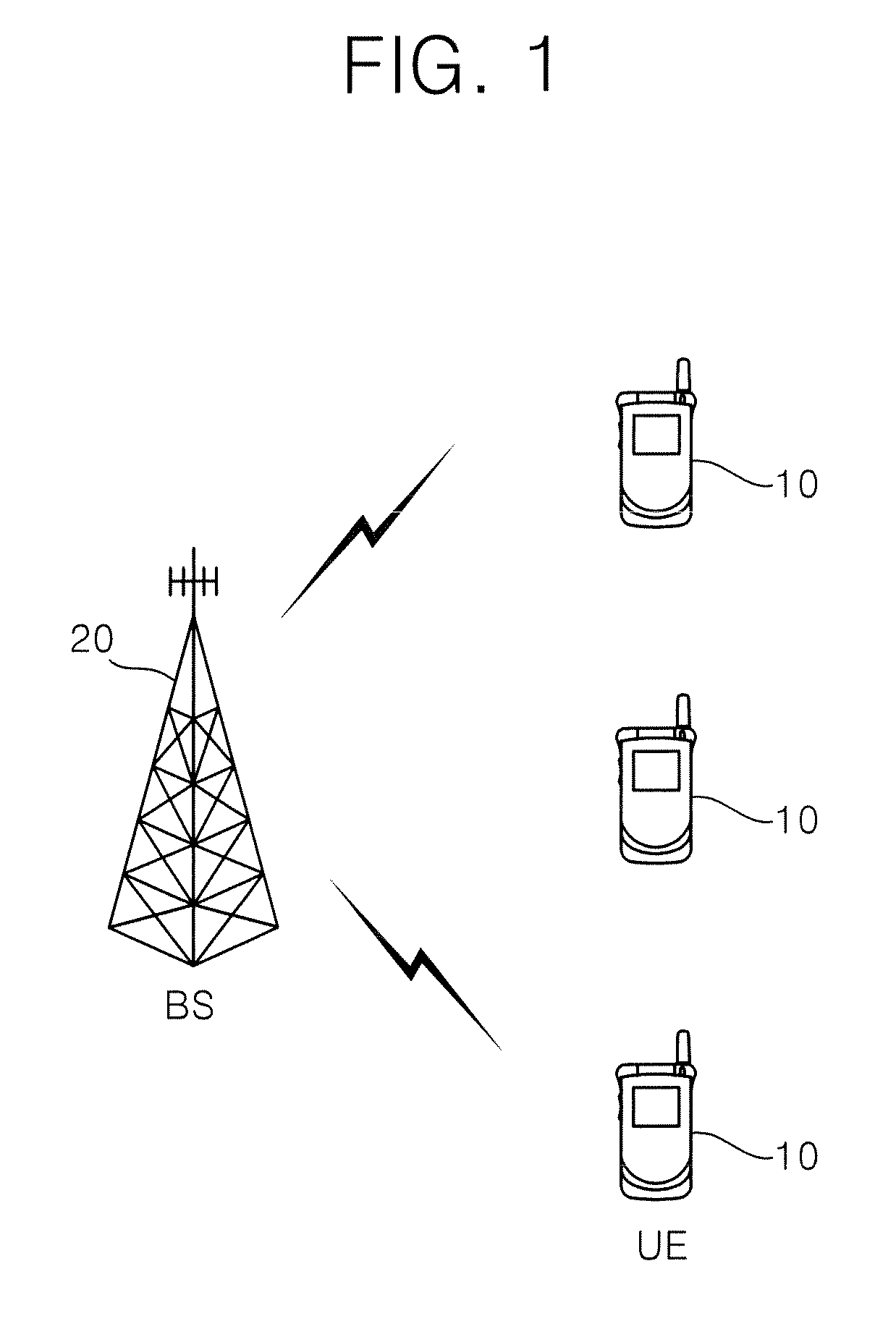
[0025]FIG. 1 shows a wireless communication system.

[0026]Wireless communication systems are widely deployed to provide a variety of communication services such as voices, packet data, and the like.

[0027]Referring to FIG. 1, the wireless communication system comprises user equipments (UEs) 10 and a base station (BS) 20. A UE 10 can be fixed or mobile and referred to as another terminology, such as a mobile station (MS), a user terminal (UT), a subscriber station (SS), a wireless device, or the like. Generally, the BS 20 is a fixed station communicating with the UE 10, which can be referred to as another terminology, such as a node-B, base transceiver system (BTS), access point, or the like. There are one or more cells within the coverage of a BS 20.

[0028]Any multiple access technique may be applied to the wireless communication system. A variety of multiple access techniques such as code division multiple access (CDMA), time division multiple access (TDMA), frequency division multipl...


PUM


Abstract

A method of transmitting data in a wireless communication system comprises receiving feedback data on an uplink data channel, the feedback data comprising a precoding matrix indicator (PMI), wherein the value of the PMI corresponds to an index in a codebook, transmitting a precoding scheme for downlink data on a downlink control channel, wherein the preceding scheme is determined as one of at least two of a transmit diversity irrespective of the received PMI, an acknowledgement indicating preceding according to the received PMI and a new PMI indicating that it is used in precoding downlink data to be transmitted, and transmitting the downlink data on a downlink data channel after applying precoding according to the determined preceding scheme.

Description

CROSS-REFERENCE TO RELATED APPLICATIONS[0001]This application claims the benefit of priority of U.S. Provisional application Ser. No. 60 / 946,130 filed on Jun. 25, 2007, U.S. Provisional application Ser. No. 60 / 978,140 filed on Oct. 8, 2007, U.S. Provisional application Ser. No. 61 / 025,304 filed on Feb. 1, 2008, Korean Patent Application No. 10-2007-0081913 filed on Aug. 14, 2007, Korean Patent Application No. 10-2007-0118166 filed on Nov. 19, 2007 and Korean Patent Application No. 10-2008-0056001 filed on Jun. 13, 2008 which are incorporated by reference in its entirety herein.BACKGROUND[0002]1. Technical Field[0003]The present invention relates to wireless communication, and more specifically, to a method of transmitting data in a multiple antenna system.[0004]2. Related Art[0005]Wireless communication systems are widely used to provide various types of communications. For example, voices and / or data are provided by the wireless communication systems. General wireless communication...

Claims


Application Information

Patent Timeline
Patent Type & Authority Applications(United States)
IPC IPC(8): H04W40/00
CPCH04B7/0413H04L2025/03802H04B7/0632H04B7/0639H04B7/0656H04B7/0689H04B7/0871H04L1/0026H04L1/0035H04L1/0073H04L1/0625H04L5/005H04L5/0053H04L25/03343H04B7/063H04B7/0619
Inventor KO, HYUN SOOIHM, BIN CHULLEE, WOOK BONGCHUNG, JAE HOONLEE, MOON IL
Owner LG ELECTRONICS INC
Why Eureka
Try Eureka