
Handling device

a technology for handling devices and payloads, applied in the field of handling payloads, can solve problems such as the path being even more difficult to control

Active Publication Date: 2009-03-05
INNOVEP
View PDF8 Cites 11 Cited by
  • Summary
  • Abstract
  • Description
  • Claims
  • Application Information

AI Technical Summary

Benefits of technology

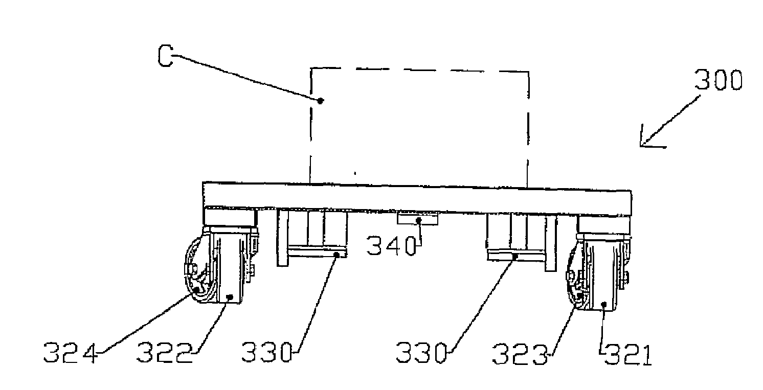
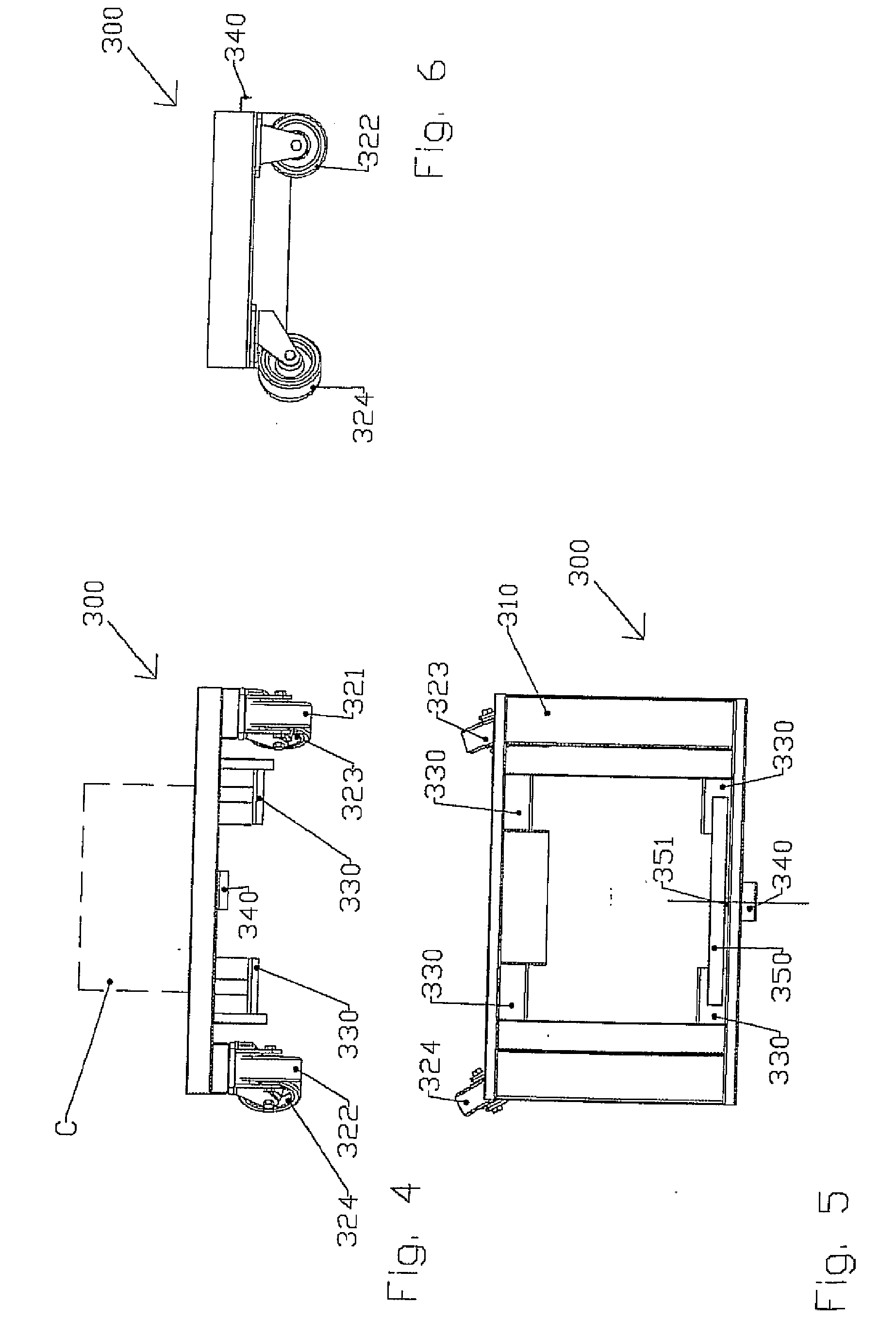
[0017]This feature is particularly advantageous in that it offers to prevent any contact between the ground and the dolly during the conveying phase. Therefore, during the conveying phase, only the rolling means for the trailer have a part in supporting the load and in the path thereof. Therefore, the rolling means for the dolly are not dimensioned for conveying, thereby reducing the cost thereof.
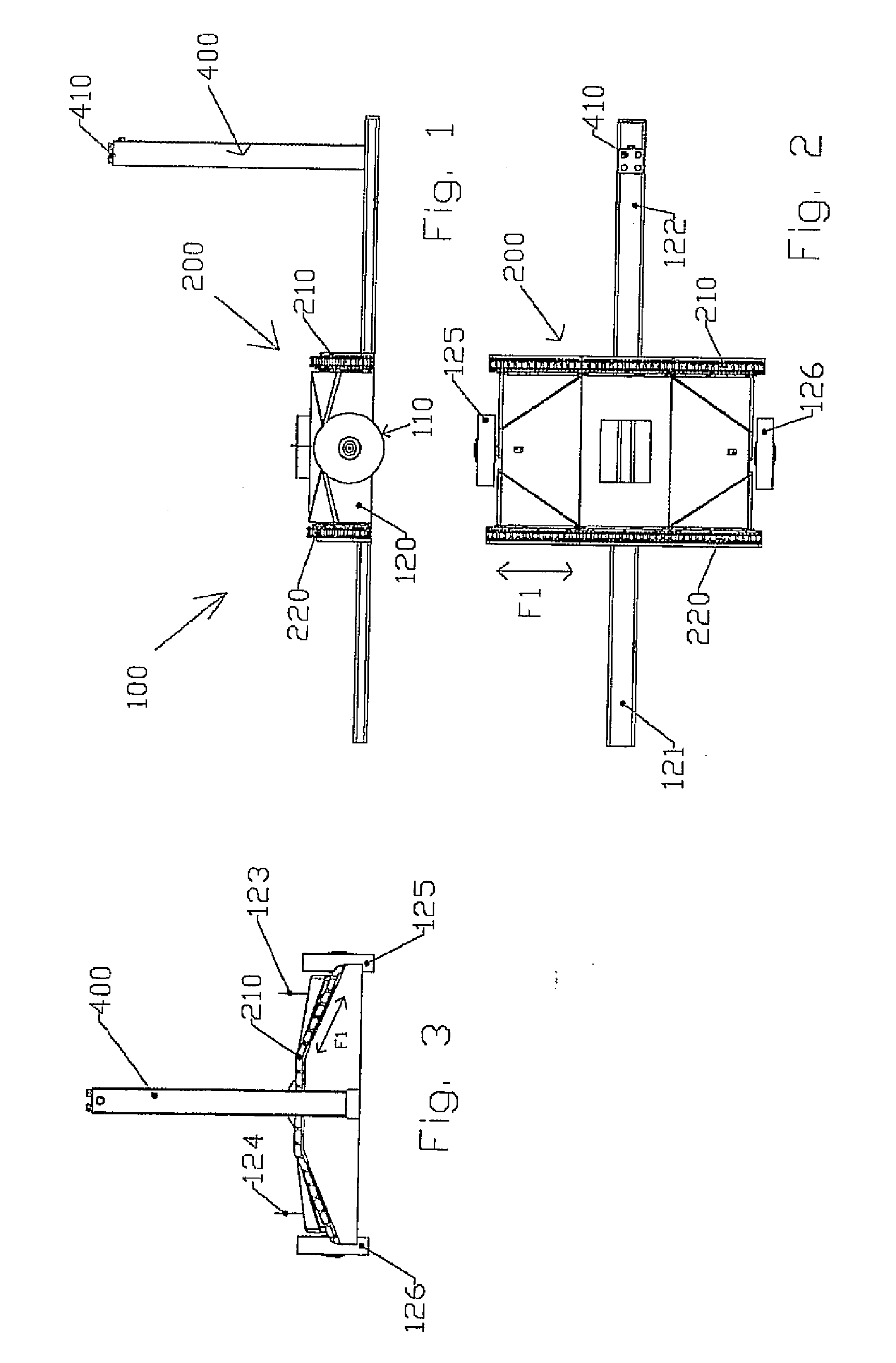
[0018]Another advantage is that the loading and unloading phases are motorized. Since the loads are particularly heavy, attaching and releasing the load-bearing dollies to and from the trailer is no longer dependent upon the physical strength of the handler. Furthermore, the use of a motorized means ensures a positioning accuracy which assists in the proper distribution of the load on the trailer and therefore proper conveyance. Motorization of this phase also makes it faster.
[0021]According to another particularly advantageous feature of the invention, said chassis is equipped on the lower portion thereof with two wheels having coaxial axle shafts comprising the rolling means for the trailer and arranged on the sides of the chassis at the centre of the trailer. In this way, it is easier to control the path of the conveyor train by means of the towing tractor, because the path of the trailers is not limited and guided by a rolling means. The orientation of these rolling means depends directly on the path followed by the towing tractor.
[0027]The trailer of the invention can thus receive a dolly via both sides thereof. Furthermore, the side via which the dolly is loaded onto the trailer does not prejudice the unloading side and allows the conveyor complete freedom.
[0029]In order to mitigate any improper driving of one chain in relation to another, during the loading and unloading phases, the applicant has advantageously devised at least two pads of the same side (front or rear) coming into contact with the chains to be mounted at the ends of a spreader beam, i.e., at the ends of an arm rotating at the centre thereof and capable of more or less raising or lowering one pad in relation to another, depending on whether or not it is contact with the chain which moves it.

Problems solved by technology

The applicant observed several disadvantages with this type of device, and included among these are the following:the trailers have four wheels, which do not enable a tandem path to be created for the conveyor train, thus complicating the manoeuvrability of a convoy such as this,the loaded dollies are difficult to load onto or unload from the chassis consisting of the trailer, this lack of mobility of the dollies being due in particular to the size of the load carried,even once loaded onto the chassis, the wheels of the dollies participate in the conveying movement, making the path even more difficult to control,the wheels of the conveyed dollies are not oriented in the direction allowing movement of the dolly relative to the chassis, for the purposes of releasing said dolly,the dollies are loaded onto said chassis with clearance space, which results in the appearance of shocks and jolts,guide means are required for the loading or unloading movements of the dolly relative to the trailer, which guide means impede the capability for mobility,in order to maintain rigidity, the chassis receiving the dolly only opens on one side, which allows access from only one side, whether for loading or unloading,etc.

Method used


Image

  • Handling device
  • Handling device
  • Handling device

Examples


Embodiment Construction

[0014]On the basis of these established facts, the applicant conducted research aiming to provide a better solution for handling loads associated with dollies.

[0015]This research resulted in the designing of a handling device based on an especially optimised association of a trailer with a dolly, which, in particular, solves the path problems of the conveyor train consisting of the trailers as well as those related to the connection of the load-bearing dolly with the trailer.

[0016]According to principal feature of the invention, the handling device combining at least one trailer capable of being hitched to a towing vehicle and / or to other trailers in order to form a conveyor train and at least one load-bearing dolly, is remarkable in that the trailer comprises rolling means supporting a chassis equipped with a loading and unloading module for the load-bearing dolly, which combines motorized means for moving the dolly and means for positioning said dolly on the chassis, whereby the d...


PUM


Abstract

The invention relates to a handling device combining at least one trailer (100) that can be hitched to a tractor vehicle and / or to other trailers to form a carriage train and at least one bed (300) for bearing the load (C), notable in that the trailer (100) comprises running means (110) supporting a chassis (120) equipped with a module (200) for loading and unloading the bed (300) that bears the load (C) combining means for the motorized movement of the bed and means for positioning said bed (300) so that the bed (300) is no longer in contact with the ground and is held in position on the trailer (100).

Description

FIELD OF APPLICATION OF THE INVENTION[0001]This invention relates to the field of handling payloads carried by dollies and, in particular, to adaptations enabling the combining of these trolleys or dollies with conveying means.DESCRIPTION OF THE PRIOR ART[0002]A plurality of handling devices exist in the prior art, which provide for the conveyance of payloads associated with dollies.[0003]Devices exist in the prior art which, in particular, propose a conveyor train trailer of the type comprising at least one load-bearing structure intended to transport at least one load, rolling means associated with this load-bearing structure and hitching means arranged so as to hitch said trailer to at least one other trailer or to a vehicle of said conveyor train. This trailer further includes a dolly which is intended to receive said load and which is detachably coupled to said chassis, said dolly comprising auxiliary rolling means so as to be movable relative to said chassis, said chassis and ...

Claims


Application Information

Patent Timeline
IPC IPC(8): B65G67/10
CPCB62D63/08B62D63/062
Inventor CAMALY, DOMINIQUE
Owner INNOVEP
Learn More