Fan

Active Publication Date: 2009-03-05
DYSON TECH LTD
View PDF97 Cites 216 Cited by
  • Summary
  • Abstract
  • Description
  • Claims
  • Application Information

AI Technical Summary

Benefits of technology

[0023]Preferably, the mouth is concentric with the interior passage. This arrangement will be visually appealing and the concentric location of the mouth with the passage facilitates manufacture. Preferably, the Coanda surface extends symmetrically about an axis. More preferably, the angle subtended between the Coanda surface and the axis is in the range from 7° to 20°, preferably around 15°. This provides an efficient primary air flow over the Coanda surface and leads to maximum air entrainment and secondary air flow.
[0024]Preferably the nozzle extends by a distance of at least 5 cm in the direction of the axis. Preferably the nozzle extends about the axis in the shape of a loop and preferably by a distance in the range from 30 cm to 180 cm. This provides options for emission of air over a range of different output areas and opening sizes, such as may be suitable for cooling the upper body and face of a user when working at a desk, for example. In the preferred embodiment the nozzle comprises a diffuser located downstream of the Coanda surface. An angular arrangement of the diffuser surface and an aerofoil-type shaping of the nozzle and diffuser surface can enhance the amplification properties of the fan assembly whilst minimising noise and frictional losses.
[0025]In a preferred arrangement the nozzle comprises at least one wall defining the interior passage and the mouth, an

Problems solved by technology

In a domestic environment it is undesirable for parts to project from the appliance, or for the user to be able to touch any moving parts of the fan, such as the blades.
However, caged blade parts can be difficult to clean and the movement of blades through air can be noisy and disruptive in a home or office environment.
A disadvantage of certain of the prior art arrangements is that the air flow produced by the fan is not felt uniformly by the user due to variations across the blade surface or across the outward facing surface of the fan.
A further disadvantage is that the cooling effect

Method used


Image

  • Fan
  • Fan
  • Fan

Examples


Example

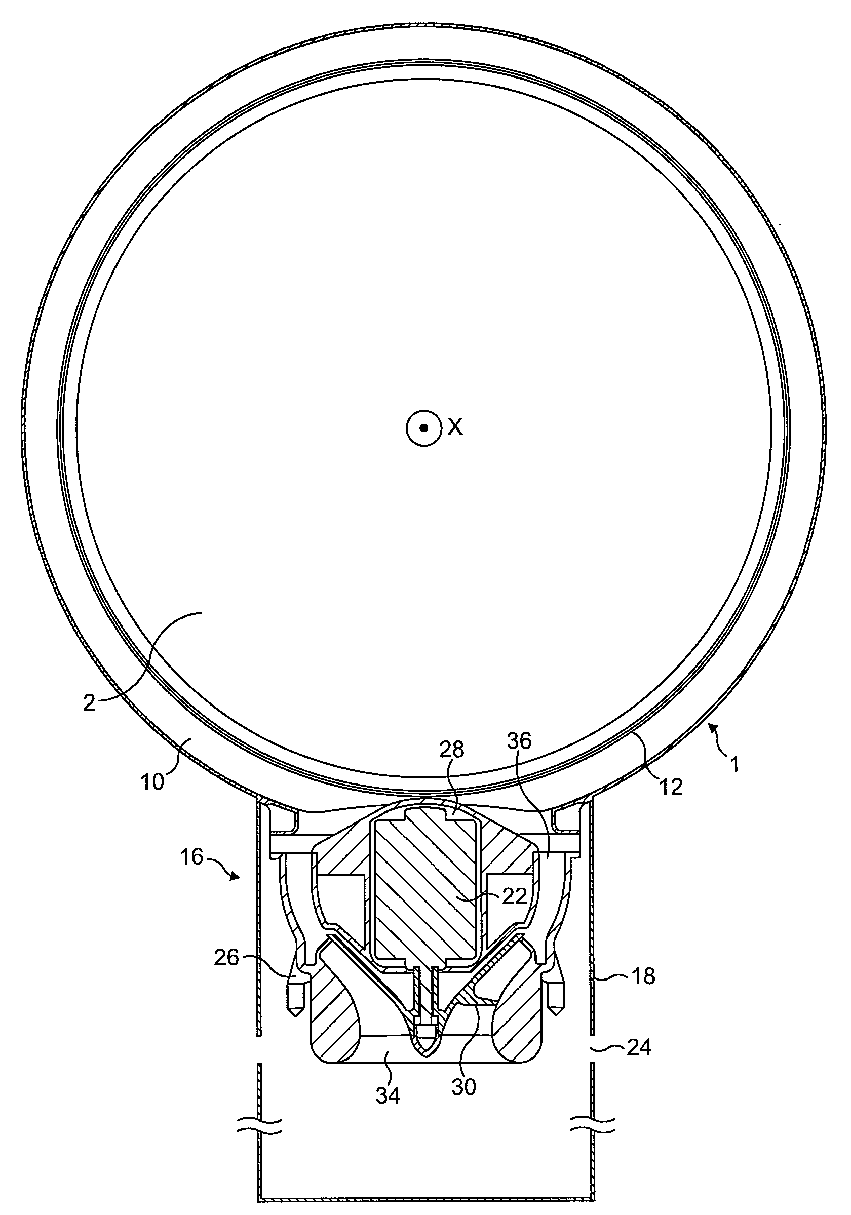
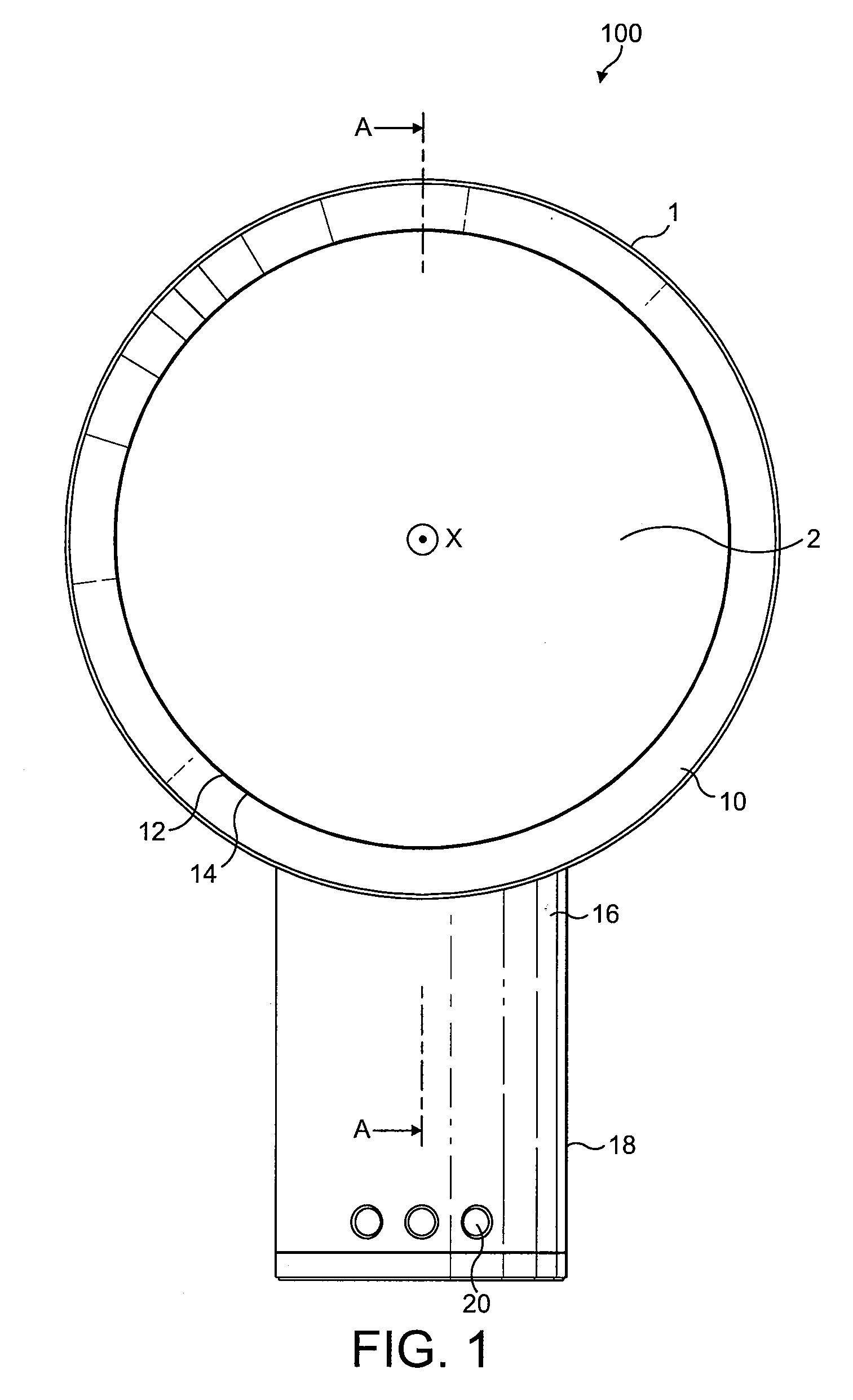
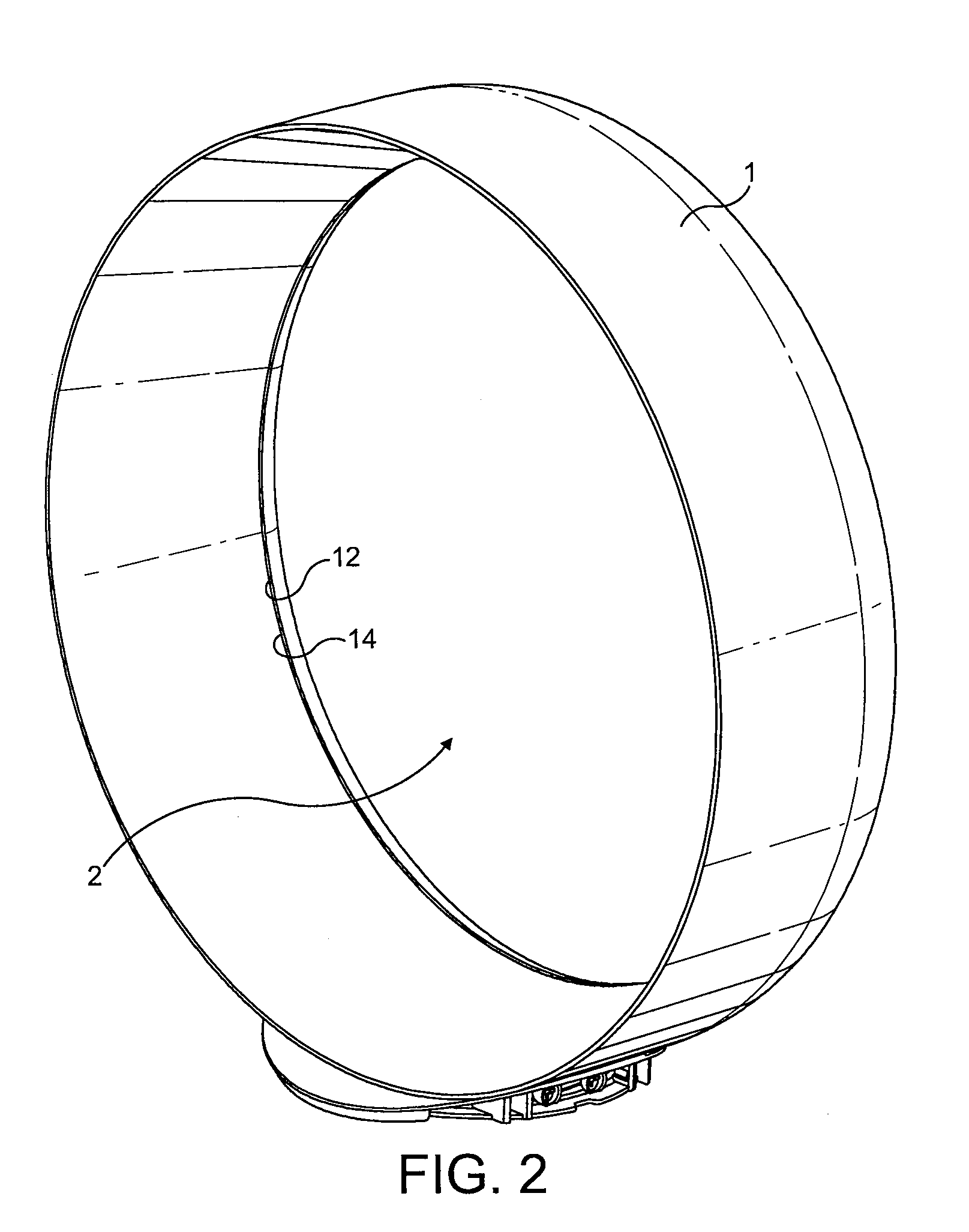
[0034]FIG. 1 shows an example of a fan assembly 100 viewed from the front of the device. The fan assembly 100 comprises an annular nozzle 1 defining a central opening 2. With reference also to FIGS. 2 and 3, nozzle 1 comprises an interior passage 10, a mouth 12 and a Coanda surface 14 adjacent the mouth 12. The Coanda surface 14 is arranged so that a primary air flow exiting the mouth 12 and directed over the Coanda surface 14 is amplified by the Coanda effect. The nozzle 1 is connected to, and supported by, a base 16 having an outer casing 18. The base 16 includes a plurality of selection buttons 20 accessible through the outer casing 18 and through which the fan assembly 100 can be operated.

[0035]FIGS. 3, 4 and 5 show further specific details of the fan assembly 100. A motor 22 for creating an air flow through the nozzle 1 is located inside the base 16. The base 16 further comprises an air inlet 24 formed in the outer casing 18. A motor housing 26 is located inside the base 16. Th...


PUM


Abstract

A fan assembly for creating an air current includes a bladeless fan assembly including a nozzle and a device for creating an air flow through the nozzle. The nozzle includes an interior passage and a mouth receiving the air flow from the interior passage. A Coanda surface located adjacent the mouth and over which the mouth is arranged to direct the air flow. The fan provides an arrangement producing an air current and a flow of cooling air created without requiring a bladed fan, that is, the air flow is created by a bladeless fan.

Description

REFERENCE TO RELATED APPLICATIONS[0001]This application claims the priority of United Kingdom Application Nos. 0717155.6, 0717148.1, 0717151.5 and 0717154.9, all filed Sep. 4, 2007, the contents of which prior applications are incorporated herein by reference.FIELD OF THE INVENTION[0002]The present invention relates to a fan appliance. Particularly, but not exclusively, the present invention relates to a domestic fan, such as a desk fan, for creating air circulation and air current in a room, in an office or other domestic environment.BACKGROUND OF THE INVENTION[0003]A number of types of domestic fan are known. It is common for a conventional fan to include a single set of blades or vanes mounted for rotation about an axis, and driving apparatus mounted about the axis for rotating the set of blades. Domestic fans are available in a variety of sizes and diameters, for example, a ceiling fan can be at least 1 m in diameter and is usually mounted in a suspended manner from the ceiling ...

Claims


Application Information

Patent Timeline
IPC IPC(8): F01D1/36F04D13/06
CPCF04D25/06F04D25/08F04F5/46F04F5/16F04D29/681F04D29/44F04D29/40F04D33/00
Inventor GAMMACK, PETER DAVIDNICOLAS, FREDERICSIMMONDS, KEVIN JOHN
Owner DYSON TECH LTD
Why Eureka
Try Eureka