Electrical connector

a technology of electrical connectors and connectors, applied in the direction of coupling contact members, coupling device connections, coupling parts, etc., can solve the problems of reducing the reliability of the connector, the electronic card may easily disconnect from the connector, and the conventional connector cannot securely engage the electronic card, etc., to achieve the effect of enhancing electrical and mechanical engagemen

Active Publication Date: 2009-03-05
ADVANCED CONNECTEK INC
View PDF5 Cites 2 Cited by
  • Summary
  • Abstract
  • Description
  • Claims
  • Application Information

AI Technical Summary

Benefits of technology

[0009]The main objective of the invention is to provide an electrical connector that provides an enhanced electrical and mechanical engagement by forming dual contacts between the electrical connector and an electronic card.

Problems solved by technology

Since each of the T-shaped or H-shaped conductive terminals only touches the electronic card at single point, the conventional connector cannot securely engage the electronic card.
When unexpected force suddenly impacts the connector, the electronic card may easily disconnect from the connector to interrupt the electronic signal transmission.
Therefore, the connector would be engaged loosely with and easily disengage inadvertently from the electronic card, accordingly reducing the reliability of the connector.

Method used


Image

  • Electrical connector
  • Electrical connector
  • Electrical connector

Examples


Embodiment Construction

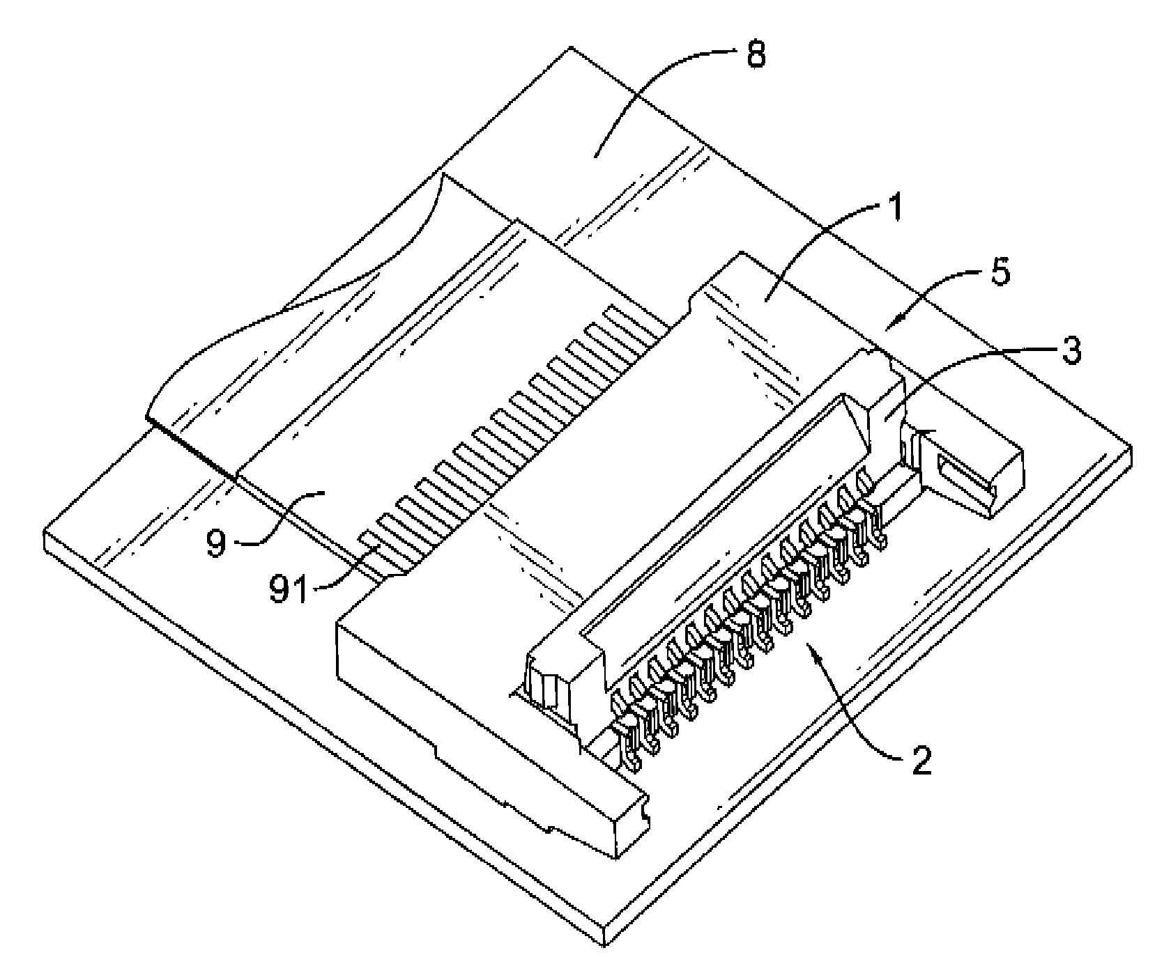
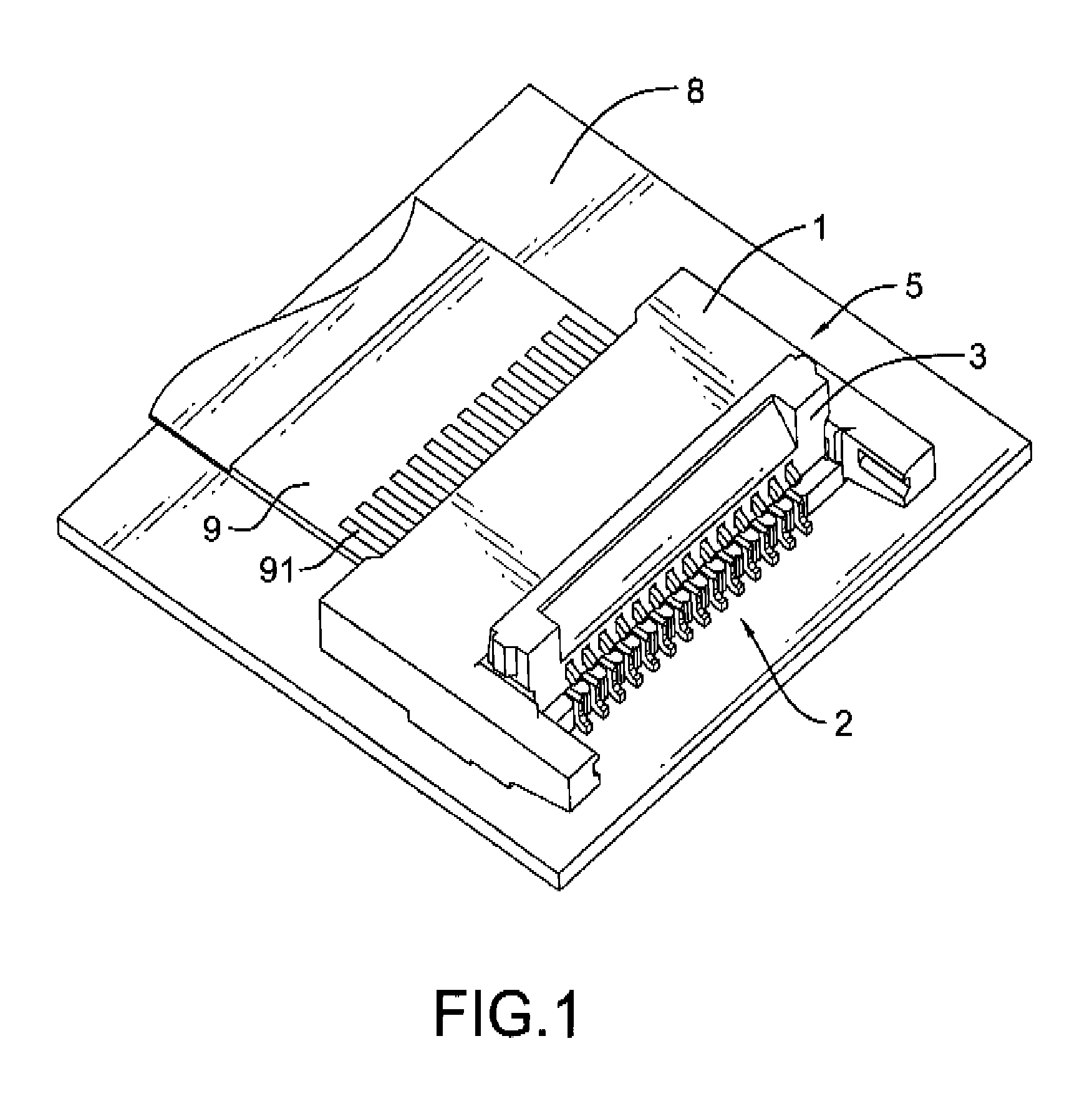
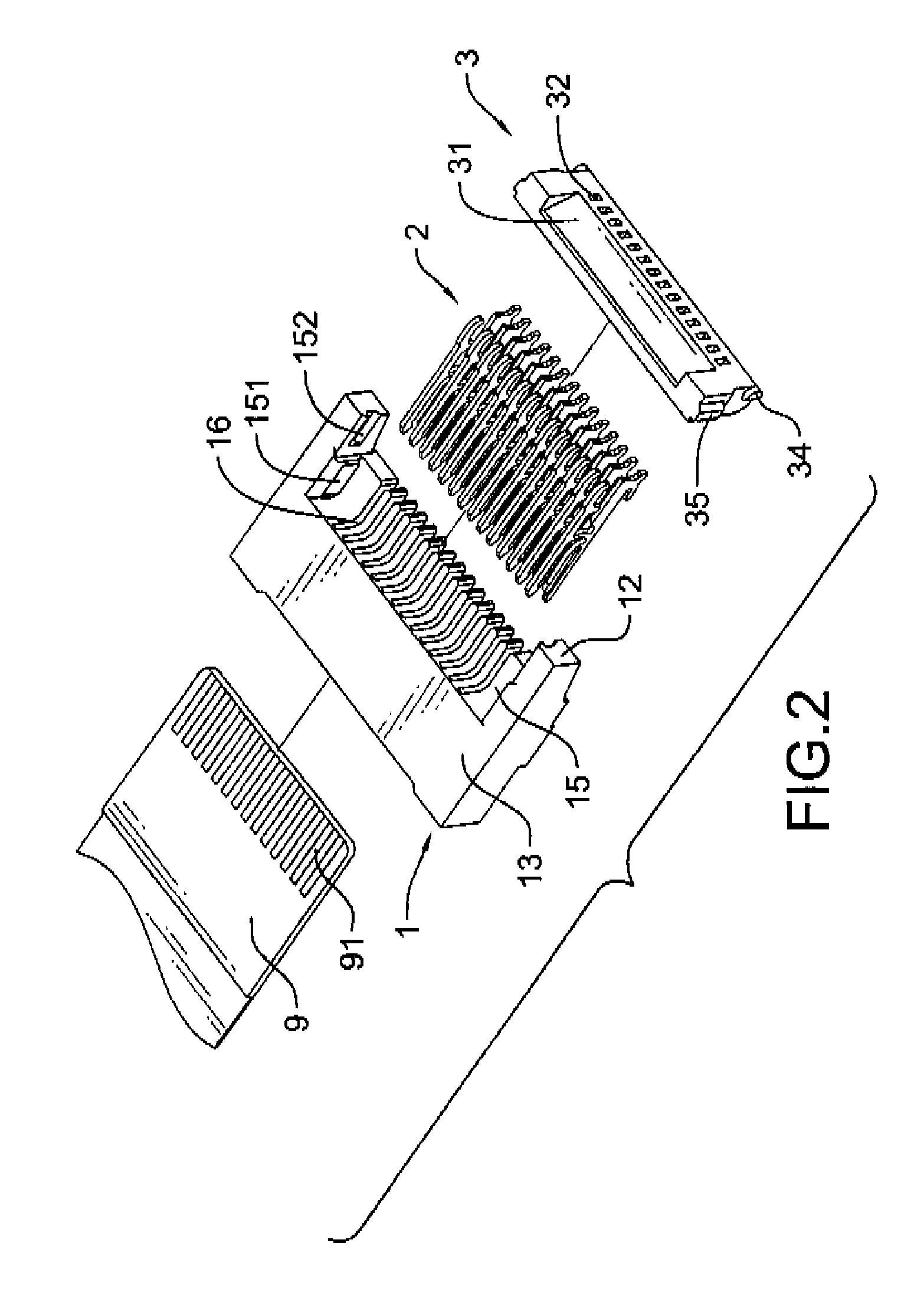
[0021]With reference to FIGS. 1, 2 and 7, an electrical connector 5 in accordance with the present invention is electrically mounted on a printed circuit board 8 and comprises an insulative housing 1, a plurality of conductive terminals 2, an operating member 3 and an optional mounting plate 4. The electrical connector 5 can electrically engage an electronic card 9 such as a flexible flat cable (FFC), a flexible printed circuits (FPC) or the like. The electronic card 9 has a plurality of conductive portions 91 formed on either a top surface or bottom surface of the electronic card 9 for signal transmission.

[0022]With further reference to FIG. 3, the insulative housing 1 has a front surface 11, a rear surface 12, a top surface 13, a slot 14, a cavity 15, a plurality of receiving spaces 16 and a blocking rib 17. The slot 14 is substantially rectangular, defined in the front surface 11 and has an inner bottom surface. The cavity 15 is defined on the top surface 13, adjacent to the rear...


PUM


Abstract

An electrical connector for engaging with an electronic card has a insulative housing with a plurality of receiving spaces, a plurality of terminals respectively mounted in the receiving spaces of the insulative housing, and an operating member pivotally connected to the insulative housing. The operating member controls the terminals in the insulative housing to be moved for electrically and mechanically engagement with the electronic card. Each of the terminals has a base portion, an upper arm and a lower arm. The upper arm is connected to the base portion at a joint as a first fulcrum. The lower arm is connected to the base portion at another joint as a second fulcrum. As the operating member pivotally moves to a predetermined position, the upper arm and the lower arm respectively rotate about the first fulcrum and the second fulcrum to securely grasp the electronic card.

Description

BACKGROUND OF THE INVENTION[0001]1. Field of the Invention[0002]The present invention relates to an electrical connector for electrically connecting to an electronic card, and more particularly to an electrical connector that electrically engages the electronic card with dual contacts.[0003]2. Description of Related Art[0004]Electronic signal connections between a conventional connector and an electronic card are implemented by T-shaped or H-shaped conductive terminals mounted in the conventional connector. Since each of the T-shaped or H-shaped conductive terminals only touches the electronic card at single point, the conventional connector cannot securely engage the electronic card. When unexpected force suddenly impacts the connector, the electronic card may easily disconnect from the connector to interrupt the electronic signal transmission.[0005]With reference to the U.S. Pat. No. 5,906,498, Nagafuji discloses an electrical connector for an electronic card. The electrical conne...

Claims


Application Information

Patent Timeline
Patent Type & Authority Applications(United States)
IPC IPC(8): H01R24/00H01R12/72H01R12/77H01R12/79H01R12/83H01R12/88
CPCH01R12/88H01R12/716
Inventor LEE, KUO-CHINGMENG, TA-TEHGUAN, JIAN-LI
Owner ADVANCED CONNECTEK INC
Why Eureka
Try Eureka