Power controller
a power controller and controller technology, applied in the direction of emergency power supply arrangements, transportation and packaging, ac network circuit arrangements, etc., can solve the problems of long recovery period of investment costs for installing power generators, consumers with little excess energy, and consumers who cannot obtain the return of reverse power flow, so as to achieve the effect of increasing the return of electricity sold
- Summary
- Abstract
- Description
- Claims
- Application Information
AI Technical Summary
Benefits of technology
Problems solved by technology
Method used
Image
Examples
embodiment 1
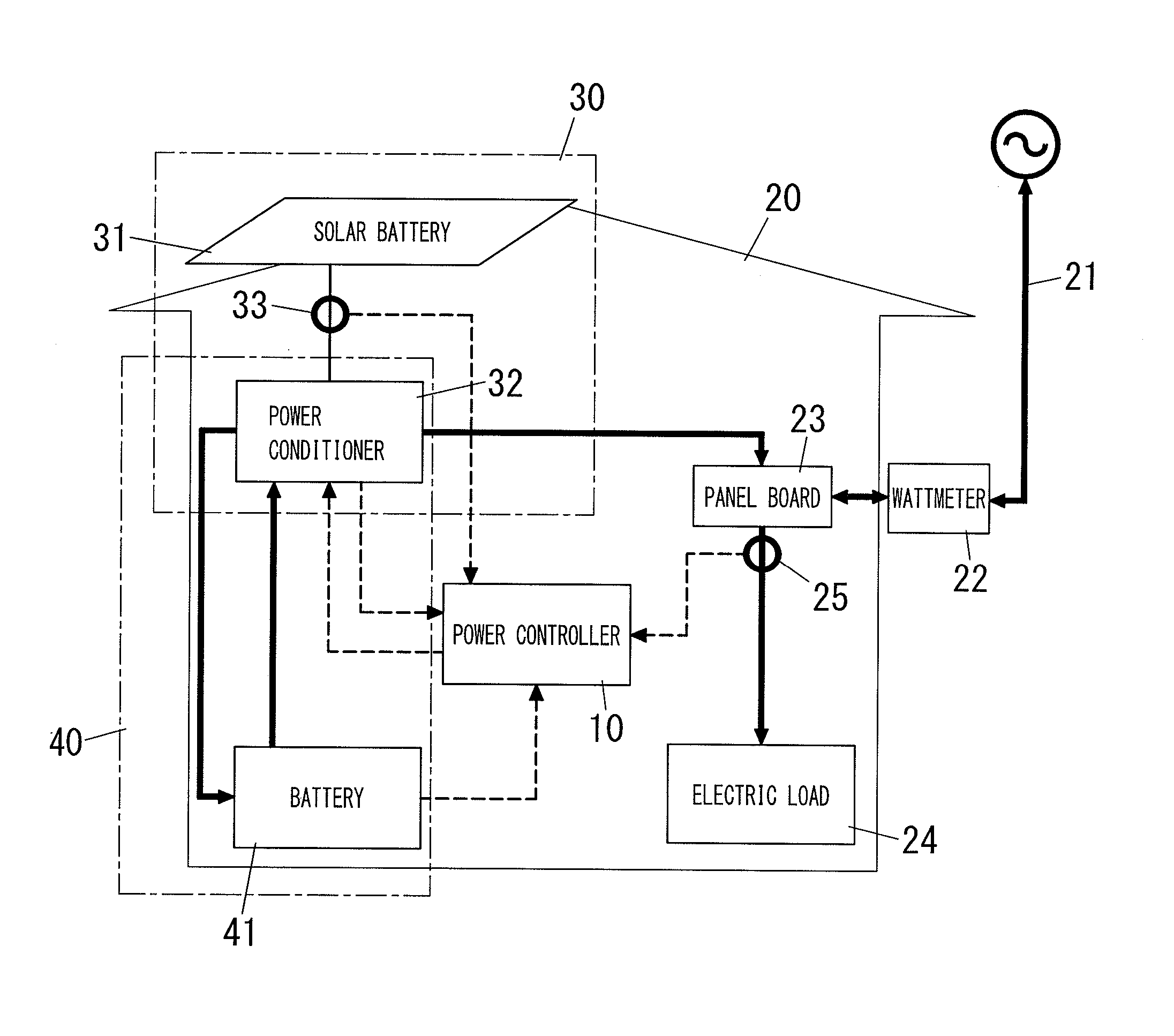
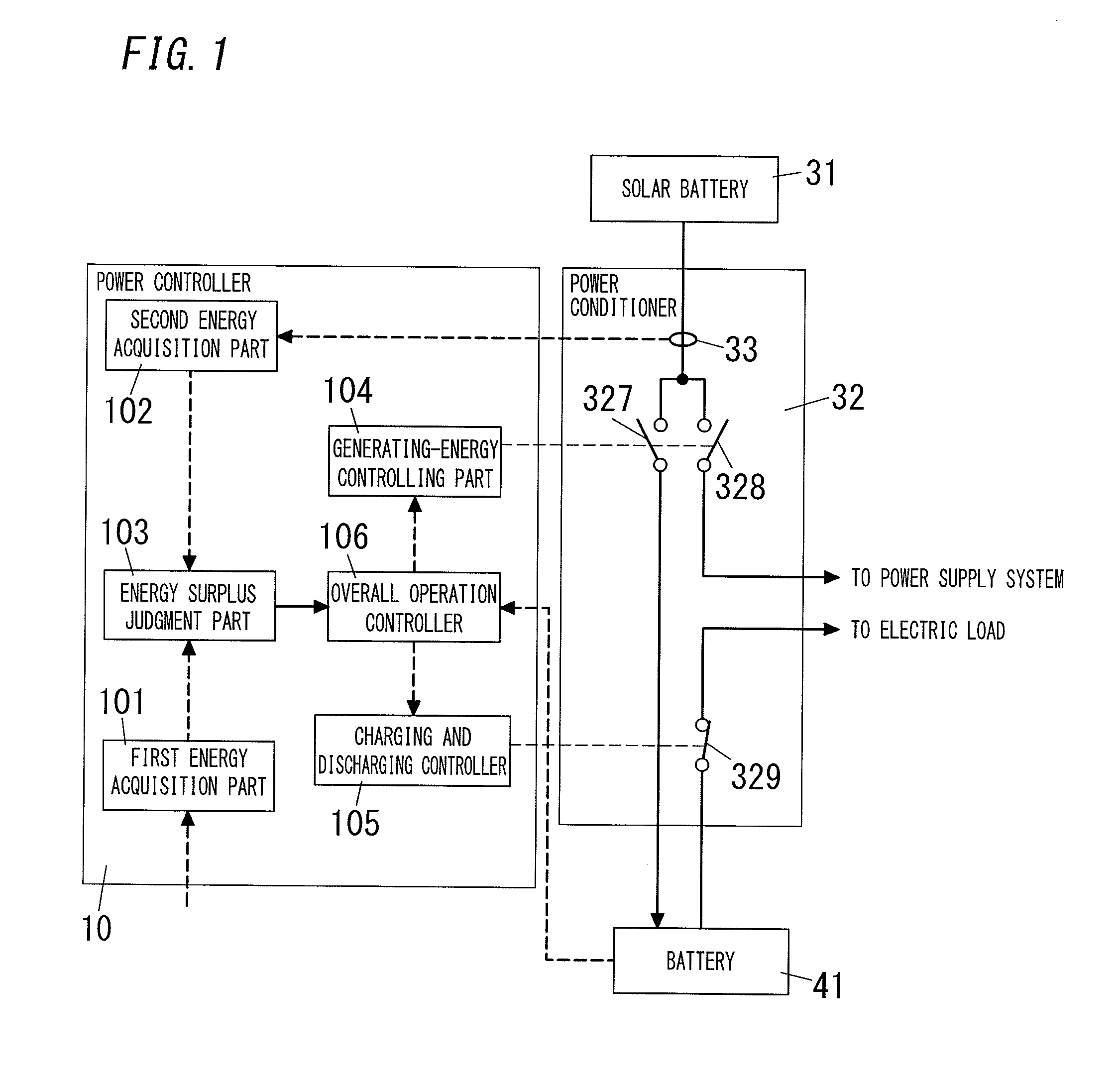
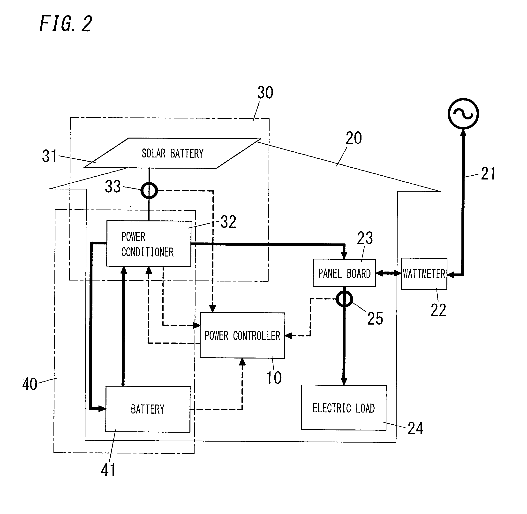
[0040]A common configuration in embodiments to be described is explained as embodiment 1. As shown in FIG. 2, a residential (dwelling) system 20 is supplied with alternating-current power through a wattmeter 22 from the power supply system 21 that is managed by an electric power utility. A panel board 23 for distributing energy to the electric loads 24 in a house is disposed in the residential system 20. The system is also provided with a demand-energy measuring means 25 configured to measure, as demand energy, a total amount of energy supplied to the electric loads 24 through the panel board 23. For example, an electronic type of energy measuring device is employed as the demand-energy measuring means 25, and configured to measure energy through a current sensor such as a current transformer and a voltage sensor for measuring a supply voltage.
[0041]In the illustrated example, the demand energy for the electric loads 24 is measured outside the panel board 23, but may be measured ins...
embodiment 2
[0085]In embodiment 1, the electrical storage device 40 is selectively charged and discharged in accordance with only the condition of presence and non-presence of the excess generating energy. The charging and discharging are therefore repeated in a period of time when the photovoltaic power system 30 produces the generating energy. Existing available batteries 41 have limitation in cycle number, because they are deteriorated by repetition of charging and discharging thereof. That is, the battery (41) life may be shortened if charging and discharging thereof are repeated.
[0086]Factors for deciding returns by selling electricity include the unit price of utility energy from the power supply system 21, and the unit price of energy flowed back to the power supply system 21. These prices may change by daily time slots or yearly seasons (exchange rates or fuel prices). In the present circumstances, the selling price of electricity is higher than the purchasing price of electricity, and ...
embodiment 3
[0096]As a general rule, embodiment 1 applies the stored energy in the electrical storage device 40 to the demand energy for the electric loads 24 when the excess generating energy is produced, and stores the generating energy of the photovoltaic power system 30 in the electrical storage device 40 when the excess generating energy is not produced. That is, the electrical storage device 40 performing any operation of charging or discharging is decided based on only the excess generating energy.
[0097]The present embodiment employs a magnitude correlation between the excess generating energy and a judgment threshold as the condition for choosing any operation of charging or discharging of the electrical storage device 40 in the energy surplus judgment part 103, and is configured to adjust the judgment threshold in response to a remaining capacity of the battery 41.
[0098]The operation of embodiment 1 corresponds to setting the judgment threshold to zero. Therefore, in embodiment 1, even...
PUM
 Abstract
Description
Claims
Application Information
 - R&D
- Intellectual Property
- Life Sciences
- Materials
- Tech Scout
- Unparalleled Data Quality
- Higher Quality Content
- 60% Fewer Hallucinations
Browse by: Latest US Patents, China's latest patents, Technical Efficacy Thesaurus, Application Domain, Technology Topic, Popular Technical Reports.
© 2025 PatSnap. All rights reserved.Legal|Privacy policy|Modern Slavery Act Transparency Statement|Sitemap|About US| Contact US: help@patsnap.com


