Electrochemical methods for wire bonding

a technology of electrochemical methods and wire bonding, which is applied in the direction of fastening means, manufacturing tools, mechanical equipment, etc., can solve the problems of difficult or expensive fabrication with traditional lithography, and achieve the effects of reducing size, improving electrical and mechanical qualities, and low cos

Inactive Publication Date: 2013-06-06
YU MIN FENG
View PDF2 Cites 19 Cited by
  • Summary
  • Abstract
  • Description
  • Claims
  • Application Information

AI Technical Summary

Benefits of technology

[0011]In an embodiment, the invention provides electrochemical probe-based methods for wire bonding. In an embodiment, the methods of the invention allow downsizing of the interconnect wire diameter to less than 1 μm and the bond size to below 3 μm, both an order of magnitude smaller than those in the current practice. The interconnect breakdown current density can be over 1011 A / m2.
[0012]The methods of the invention are not limited only to fabricating interconnect bridges with significantly reduced sizes and improved electrical and mechanical qualities that can potentially meet the challenges in electronics industry. As it is intrinsically an 3-D micro and nanofabrication technology, with the proper mechanical design and system control, it can be utilized to fabricate more intricate microscale and nanoscale structures of designed structural and device functionalities integrating a variety of metallic materials, such as magnetic and noble metals and even metal alloys. Moreover, as it is intrinsically a low cost direct-writing technology, this technique can be used to fabricate such micro- / nano-structures on existing micro- / nano-structures, which would otherwise be very difficult or expensive to fabricate with a traditional lithography process

Problems solved by technology

Moreover, as it is intrinsically a low cost direct-writing technology, this technique can be used to fabricate such micro- / nano-structures on existing micro- / nano-structures, which would otherwise be very difficult or expensive to fabricate with a traditional lithography process

Method used


Image

  • Electrochemical methods for wire bonding
  • Electrochemical methods for wire bonding
  • Electrochemical methods for wire bonding

Examples


example 1

Fabrication of Nanostructures

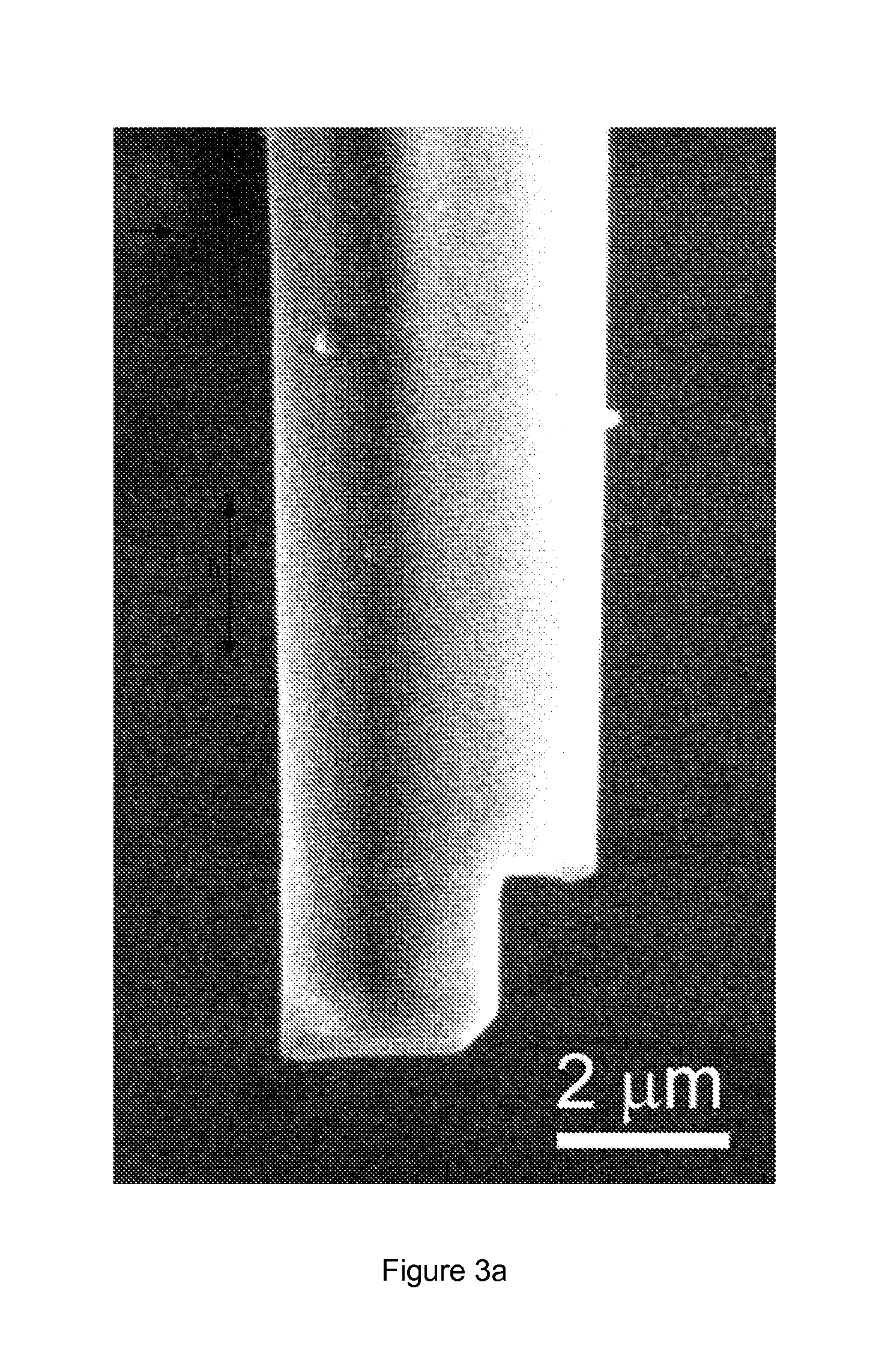
[0136]FIG. 4 shows a series of angled Cu wires grown with a side-cut nozzle as shown in FIG. 3a. The vertical and lateral lengths as well as the orientation of the Cu wires were controlled by the travel path of the micropipette, and the diameter determined by the nozzle size and the size of the side opening in the nozzle. To fabricate these structures, a micropipette filled with a simple 0.05 M CuSO4 aqueous solution with no other additives was used and biased at 0.2 V with respect to the Au-coated sample surface. The micropipette had a nozzle diameter of ˜3 μm and had a side cut made with the focused ion beam machining. The growth rate for the Cu wire at those conditions was ˜0.25 μm / s, and the corresponding ionic current was maintained at ˜3.5 nA. The deposition was carried out with the substrate exposed to a humidity controlled ambient air environment at room temperature.

[0137]FIGS. 9A-D illustrates various structures made using meniscus-confined elec...

example 2

Interconnect Bridge Fabrication

[0138]To facilitate the interconnect bridge fabrication with a method that involves the lateral growth of a metallic wire over a sufficient span, the micropipette nozzle was shaped to allow additionally the stable meniscus formation sideway to the nozzle during the lateral growth of metallic wire. FIG. 3a shows a typical shaped micropipette nozzle having a nozzle diameter of about 3 μm. Micropipettes having other nozzle diameters can also be shaped depending on the size of the wire to be fabricated. For fabricating Cu wire bonds, typically a simple 0.05 M CuSO4 aqueous solution with no other additives was used and filled into a micropipette and biased at 0.2 V with respect to the conductive sample surface. The deposition was carried out with the substrate exposed to a humidity controlled ambient air environment at room temperature.

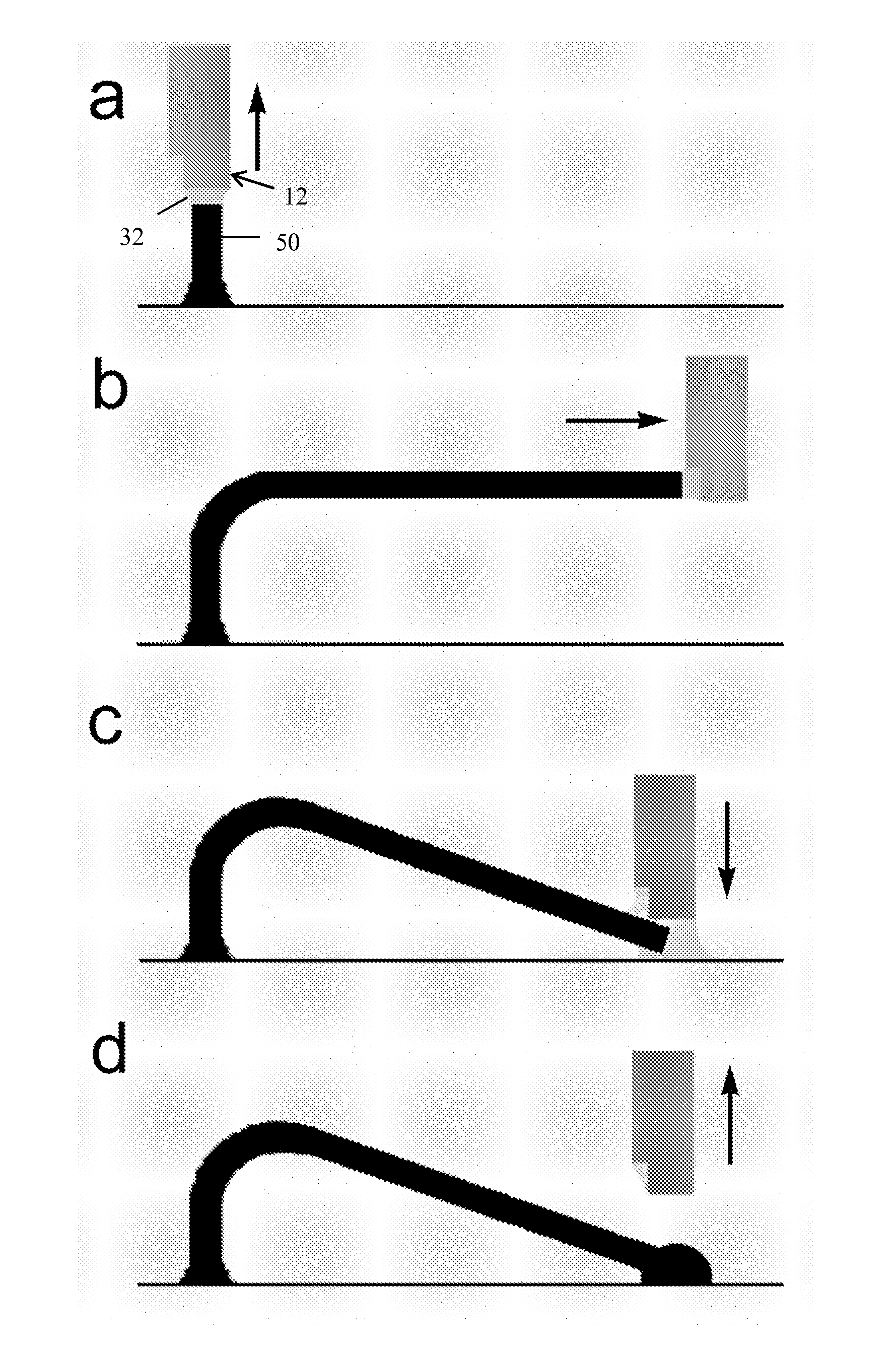
[0139]To complete a wire bonding process (as schematically described in FIGS. 6a-d), the second bond was formed by mechanic...

example 3

Meniscus Stability Calculations

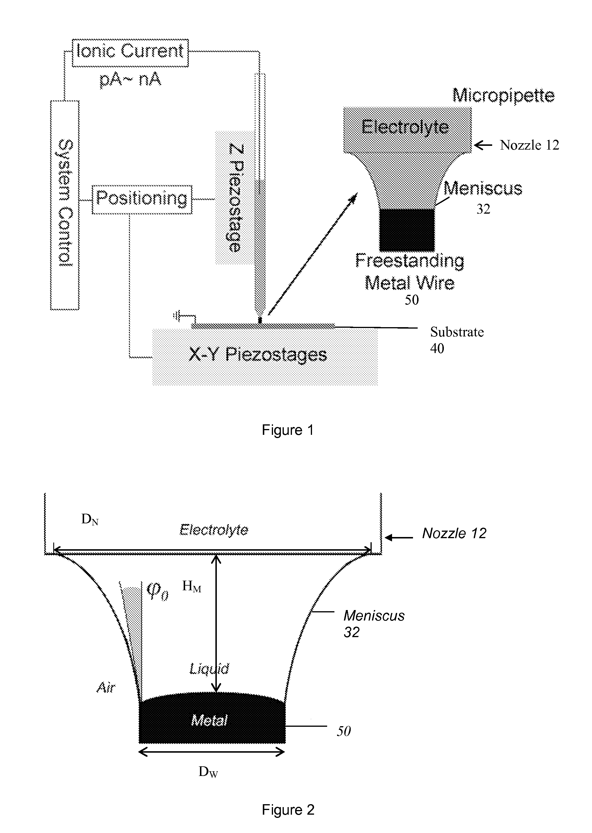
[0145]To maintain the growth of a uniform diameter wire, the thermodynamic consideration of the interfacial forces at the three-phase contact line between the meniscus and the growing wire requires the classical Neumann quadrilateral relation to be met(18), which would then require the establishment of an equilibrium angle φ0 between the growth direction and the slope of the meniscus at the contact line (as shown in the inset in FIG. 1 and in FIG. 2):

φ0=arccos[γL2+γS2−γSL2) / 2γLγS],   (1)

Where γL and γS are the surface energies of the electrolyte and the metal wire and γSL is the interfacial energy of the metal / liquid interface. This angle is determined to be ˜12° for the copper-water-air system (taking γL=0.07119 J / m2, γS=0.71±0.18 J / m2, γSL=0.01456 J / m2)(19, 20). Solving the meniscus shape equations then defines that there exists a region of stability for the stable growth of a uniform diameter wire governed by (21):

HMDW=12cosϕ0[cosh-1DNDWcosϕ0-cosh-1...


PUM

PropertyMeasurementUnit
sizeaaaaaaaaaa
pressureaaaaaaaaaa
humidityaaaaaaaaaa

Abstract

Probe-based methods are provided for wire bonding and joining of structures. The wire bonds are formed via a meniscus-confined electrodeposition technique. The electrodeposition technique of the invention can also be used for fabricating one or more nano-sized or micro-sized elongated structures. The structures extend at least partially upwards from the surface of a substrate, and may extend fully upward from the substrate surface. Apparatus suitable for use with the electrodeposition technique are also provided.

Description

CROSS REFERENCE TO RELATED APPLICATIONS[0001]This application claims the benefit of U.S. Provisional Application No. 61 / 352,590, filed Jun. 8, 2010, which is hereby incorporated by reference in its entirety.BACKGROUND[0002]With the ever-increasing device density in electronic chips, the density of interconnects and the complexity involved in the design of interconnects grow exponentially. Moreover, with the introduction of the 3-D chip, while the inter-chip vias technology(1) offers a viable solution to integrate devices in 3-D stacks, alternative interconnect technologies that can provide flexible means to electrically wire microscale device components in 3-D are still called for. As a traditional technology, the wire bonding technology has served the electronics industry for many decades, satisfying the interconnection needs for device packaging(2). Recently, to increase the interconnect density and improve device performance for high frequency operation, the flip-chip interconnec...

Claims


Application Information

Patent Timeline
Patent Type & Authority Applications(United States)
IPC IPC(8): H01R43/02
CPCC25D1/04Y10T403/478C25D5/08C25D17/02C25D17/12H01L24/43H01L24/48H01L24/49H01L24/85H01L2224/43H01L2224/45144H01L2224/45147H01L2224/45164H01L2224/45169H01L2224/48092H01L2224/48599H01L2224/49109H01L2224/78301H01L2224/851H01L2924/01013H01L2924/01015H01L2924/01028H01L2924/01029H01L2924/01046H01L2924/01047H01L2924/01073H01L2924/01077H01L2924/01078H01L2924/01079H01L2924/01082H01L2924/014C25D5/06H01R43/0235H01L2924/01075H01L2924/01074H01L2924/01072H01L2924/01041H01L2924/0104H01L2924/01033H01L2924/01005H01L2924/01006H01L2924/01019H01L2924/01023H01L2924/00014H01L2224/45015H01L2224/05599H01L2224/85399H01L24/45H01L2924/00H01L2924/2075H01L2924/20751H01L2924/00015
Inventor YU, MIN-FENG
Owner YU MIN FENG
Why Eureka
Try Eureka