
Discharge electrode and method for enhancement of an electrostatic precipitator

a technology of electrostatic precipitator and discharge electrode, which is applied in the direction of electrostatic separation, solid separation, chemistry apparatus and processes, etc., can solve the problems of difficulty in achieving reducing the efficiency of electrostatic precipitators, and not working as well as is desired, so as to improve the collection efficiency and improve the collection efficiency. , the effect of enhancing the electric field

Inactive Publication Date: 2007-07-05
BABCOCK & WILCOX POWER GENERATION GRP INC
View PDF19 Cites 22 Cited by
  • Summary
  • Abstract
  • Description
  • Claims
  • Application Information

AI Technical Summary

Benefits of technology

[0008] The discharge electrode for the electrostatic precipitator includes geometric features incorporated into the discharge electrode and adapted according to an algorithm for improving collection efficiency for particles by enhancing an electric field between the discharge electrode and a collection electrode of the electrostatic precipitator.
[0009] The method for producing a discharge electrode for an electrostatic precipitator includes stages for selecting an algorithm for evaluation of the collection efficiency of the electrostatic precipitator; and incorporating geometric features into the discharge electrode according to the algorithm, wherein the geometric features improve the collection efficiency by enhancing the charging and collecting electric field between the discharge electrode and the collection electrode of the electrostatic precipitator.
[0010] The electrostatic precipitator includes at least one discharge electrode having geometric features incorporated into the discharge electrode and adapted according to an algorithm for improving collection efficiency for particles by enhancing an electric field between the discharge electrode and the collection electrode of the electrostatic precipitator.

Problems solved by technology

However, in some instances, electrostatic precipitators do not work as well as is desired.
For example, electrostatic precipitators are not as effective with discharge streams having particles with a high electrical resistivity.
Further challenges to the efficiency arise as users increase flow rates through the collection chamber in order to meet increased production (discharge) needs.

Method used


Image

  • Discharge electrode and method for enhancement of an electrostatic precipitator
  • Discharge electrode and method for enhancement of an electrostatic precipitator
  • Discharge electrode and method for enhancement of an electrostatic precipitator

Examples


Embodiment Construction

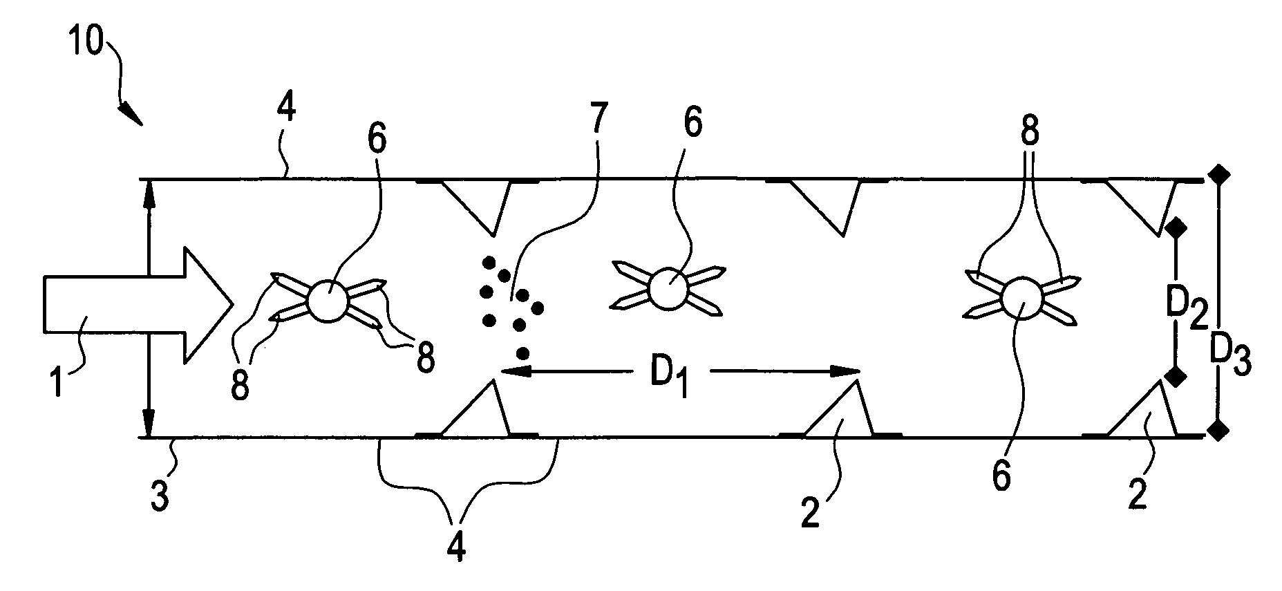
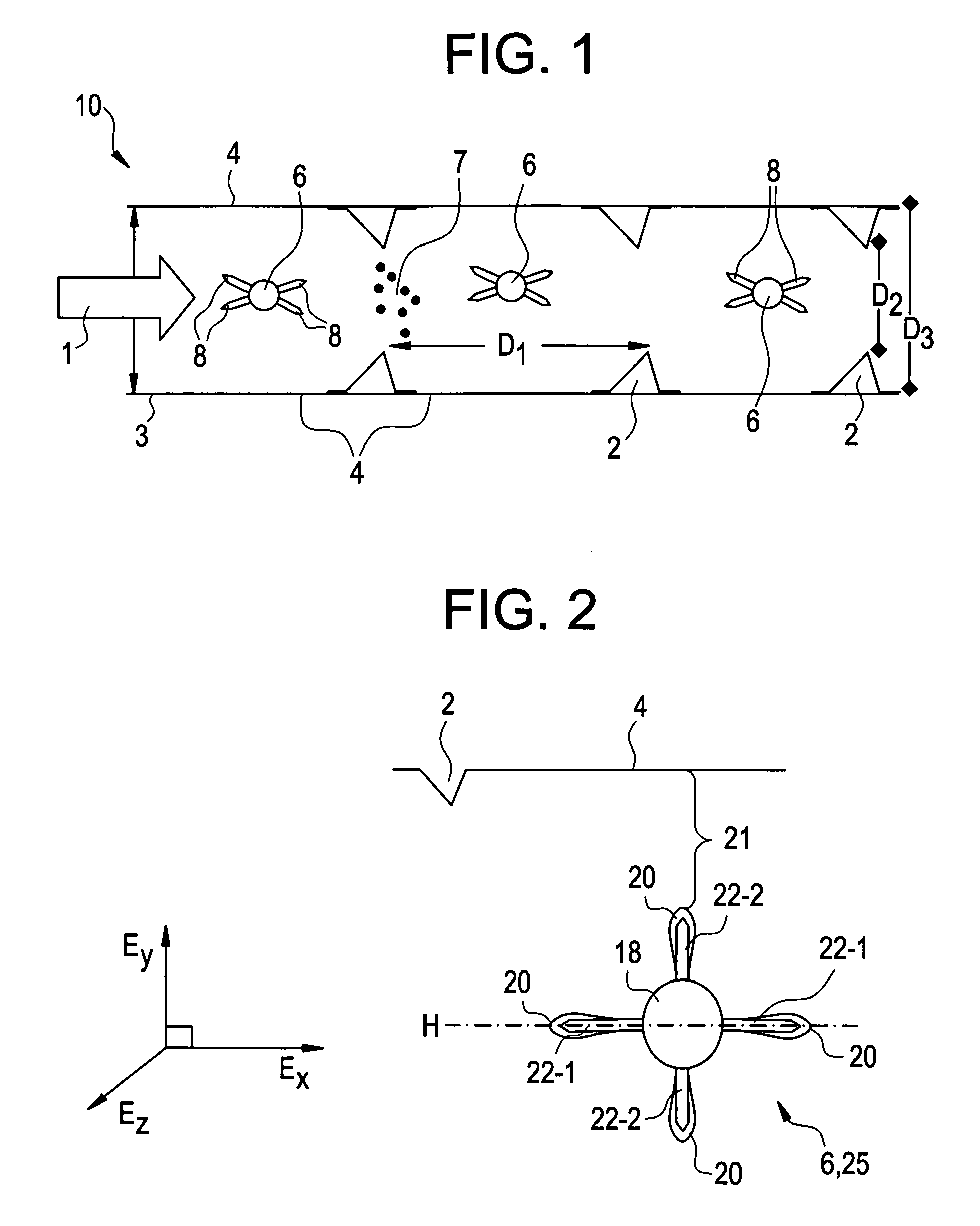
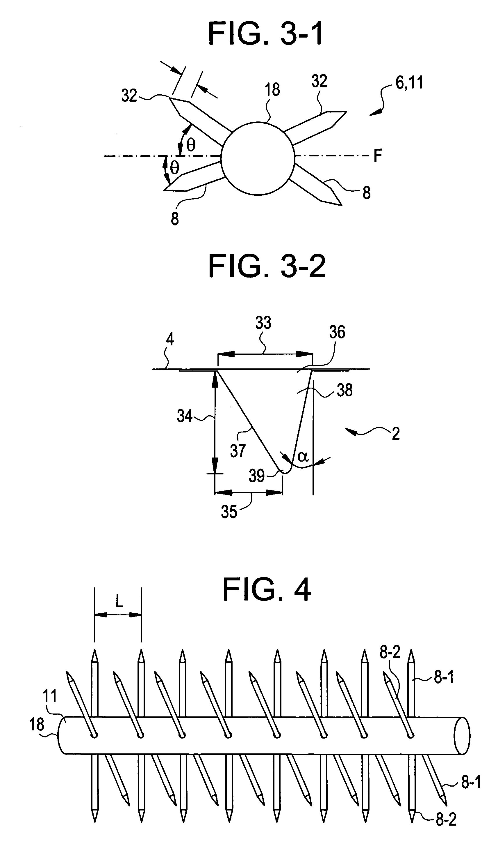
[0024] Referring to FIG. 1, there is shown an exemplary embodiment of an electrostatic precipitator 10 including improvements as disclosed herein. The electrostatic precipitator 10 is typically a planar structure that includes a series of parallel and generally flat collecting plates 4 more or less evenly spaced, with discharge electrodes 6 located periodically between the collecting plates 4. Typically included in the electrostatic precipitator 10 are a series of stiffeners 2. During operation, collecting plates 4 attract and collect particles 7 entrained in the emission gas 1. As is known in the art, a high voltage is applied across the discharge electrodes 6 and the collecting plates 4 to generate an electric field. Once in the electric field, the particles 7 generally become negatively charged and migrate toward the collecting plates 4 (also referred to as “collecting electrodes 4”). This migration occurs, at least in part, as a result of the negative discharge corona (not shown...


PUM


Abstract

Apparatus and method for producing an electrostatic precipitator that includes a discharge electrode having an enhanced design, the enhanced design for improving an electric field and particulate collection efficiency within the electrostatic precipitator.

Description

BACKGROUND OF THE INVENTION [0001] This invention relates generally to electrostatic precipitators, and more specifically to techniques for improving the collection efficiency thereof. [0002] Many industrial facilities require devices for limiting environmental emissions of particulate materials. A well-known device is the electrostatic precipitator. Electrostatic precipitators are commonly used in the electric utility industry at power production facilities (to limit emission of combustion by-products). Other examples of industries using electrostatic precipitators include those fabricating cement (dust), pulp and paper products (salt cake and lime dust), petrochemicals (for various mists), and steel (dust and fumes). [0003] Electrostatic precipitators direct a stream of particle-laden gases through a collector chamber. The collector chamber contains electrodes that act as particle collectors. In a typical design, discharge electrodes are electrically insulated from the rest of the...

Claims


Application Information

Patent Timeline
Patent Type & Authority Applications(United States)
IPC IPC(8): B03C3/41
CPCB03C3/41B03C2201/10B03C2201/08
Inventor TAYLOR, ROBERTYOUNSI, ABDELKRIMZHOU, YINGNENGJOHNSTON, DAVIDFARMER, TERRYROBERTS, J. EASEL
Owner BABCOCK & WILCOX POWER GENERATION GRP INC
Learn More