Endoscope apparatus
a technology of endoscope and endoscope, which is applied in the field of endoscope equipment, can solve the problems of insufficient reduction operation, inability to ensure the grip of all the intestines having such diverse inner diameters, and inability to properly insert the endoscop
- Summary
- Abstract
- Description
- Claims
- Application Information
AI Technical Summary
Benefits of technology
Problems solved by technology
Method used
Image

Examples
first embodiment
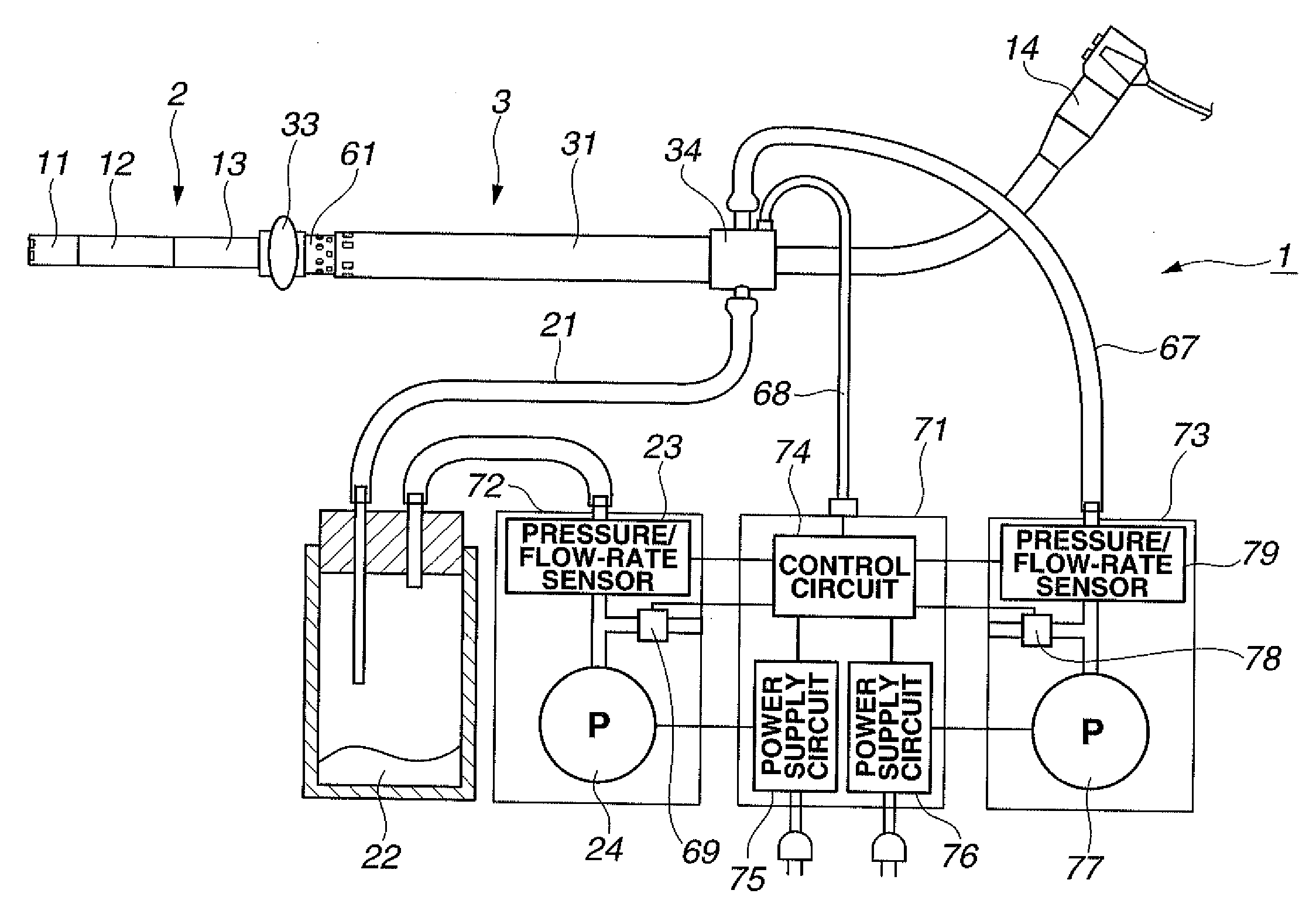
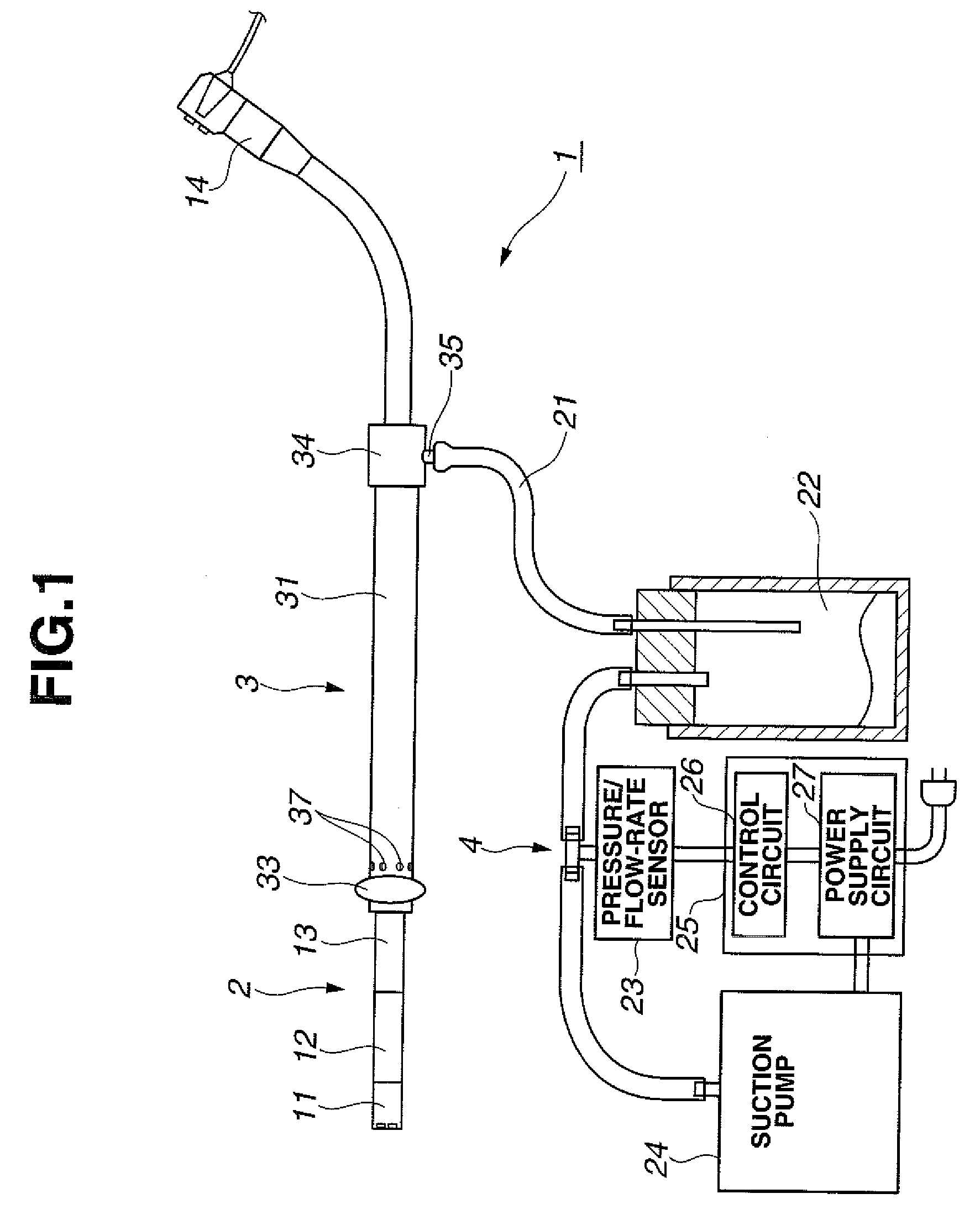
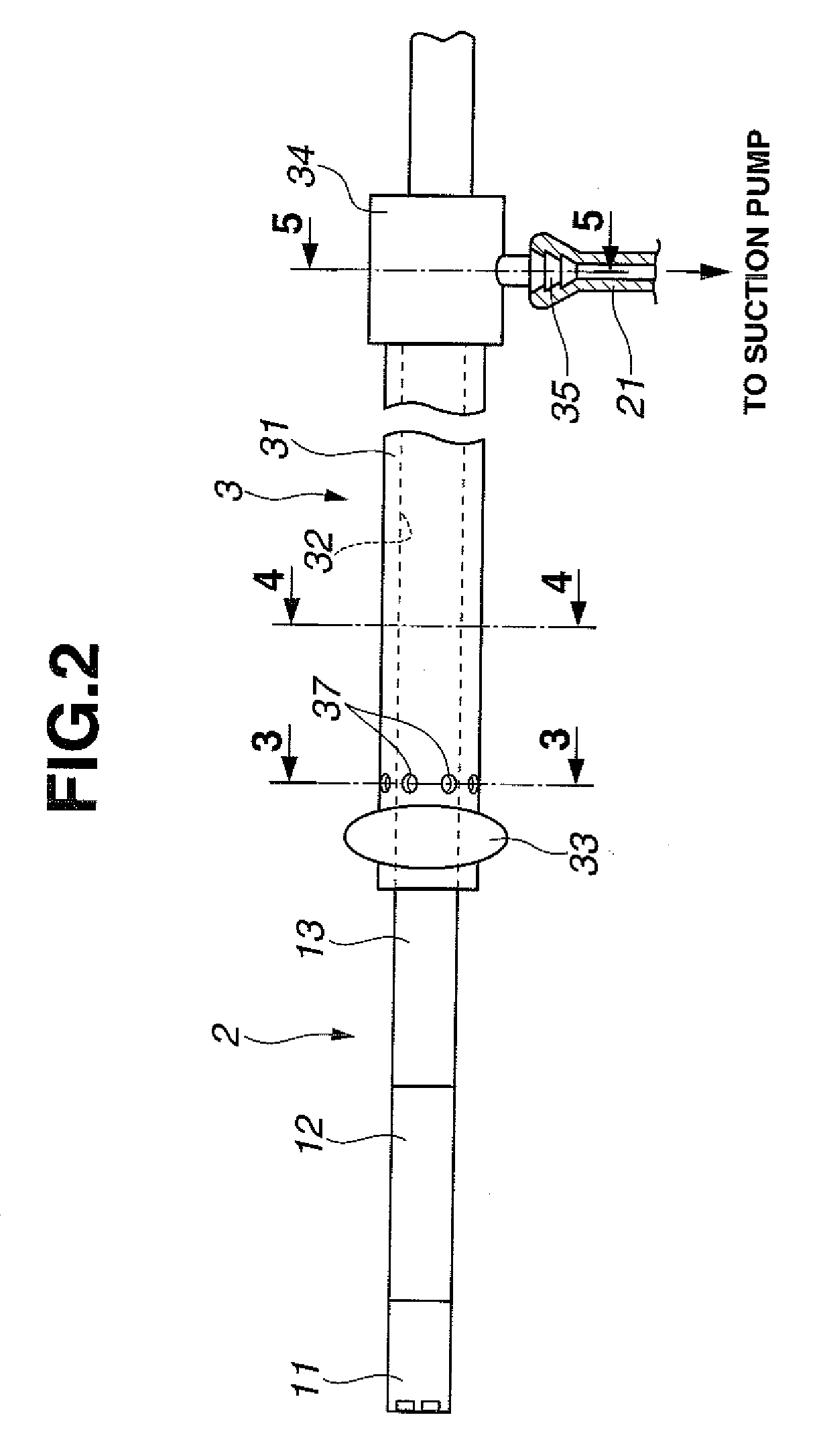
[0042]FIGS. 1 to 10 illustrate a first embodiment of the present invention, in which FIG. 1 is a diagram illustrating configuration of an endoscope apparatus, FIG. 2 is a diagram illustrating configuration of a scope and an over tube in more detail, FIG. 3 is a 3-3 sectional view of FIG. 2 illustrating the configuration of the over tube, FIG. 4 is a 4-4 sectional view of FIG. 2 illustrating the configuration of the over tube, FIG. 5 is a 5-5 sectional view of FIG. 2 illustrating the configuration of the over tube, FIG. 6 is a diagram illustrating a state where the scope and the over tube are inserted into a lumen, FIG. 7 is a diagram illustrating a state where the scope and the over tube are inserted into the lumen for suctioning, FIG. 8 is a diagram illustrating a state where the scope and the over tube inserted into the lumen in a suctioning state are pulled so as to make the lumen straight, FIG. 9 is a diagram illustrating a state where the scope is relatively advanced and insert...
second embodiment
[0074]FIGS. 11 and 12 show a second embodiment of the present invention, in which FIG. 11 is a diagram illustrating configuration of the scope and the over tube, and FIG. 12 is a diagram illustrating a state in the vicinity of the scope and the over tube when a fluid is being suctioned. In the second embodiment, the same reference numerals are given to the portions similar to those in the first embodiment and the description will be omitted, and only the differences will be mainly described.
[0075]The over tube 3 in the present embodiment has, as shown in FIG. 11, a second balloon 38 as a large-diameter portion is further provided at the proximal end side of the suction opening portion 37 in addition to the configuration of the first embodiment.
[0076]With such configuration, if a fluid is suctioned from the suction opening portion 37, when the intestine 101 as a lumen is drawn the suctioned fluid is mainly a fluid in the intestine 101 between the first balloon 33 and the second ballo...
third embodiment
[0078]FIG. 13 shows a third embodiment of the present invention and is a diagram illustrating configuration of the scope and the over tube. In the third embodiment, the same reference numerals are given to the portions similar to those in the first and second embodiments and the description will be omitted, and only the differences will be mainly described.
[0079]In the present embodiment, the suction opening portion 37 is provided in plural at different positions in a direction of an insertion axis. That is, the over tube 3 of the present embodiment is configured substantially similarly to that of the first embodiment, but the plurality of suction opening portions 37 disposed in the circumferential direction are disposed in plural pairs at different positions in the insertion-axis direction.
[0080]Action of the third embodiment is substantially similar to that of the first embodiment.
[0081]According to such third embodiment, substantially similar advantages to those of the above firs...
PUM
 Abstract
Description
Claims
Application Information
 - Generate Ideas
- Intellectual Property
- Life Sciences
- Materials
- Tech Scout
- Unparalleled Data Quality
- Higher Quality Content
- 60% Fewer Hallucinations
Browse by: Latest US Patents, China's latest patents, Technical Efficacy Thesaurus, Application Domain, Technology Topic, Popular Technical Reports.
© 2025 PatSnap. All rights reserved.Legal|Privacy policy|Modern Slavery Act Transparency Statement|Sitemap|About US| Contact US: help@patsnap.com