Ice coated hypodermic needle

a hypodermic needle and ice coating technology, applied in the field of frozen water coated hypodermic needles, can solve the problems of old and obvious, use of cold surfaces and cryogenic fluids to cool the skin

Inactive Publication Date: 2009-03-05
SUN WILLIAM Y
View PDF20 Cites 93 Cited by
  • Summary
  • Abstract
  • Description
  • Claims
  • Application Information

AI Technical Summary

Problems solved by technology

The use of cold surfaces and cryogenic fluids to cool the skin where injection or cutting is to take place per se is old and obvious.

Method used


Image

  • Ice coated hypodermic needle
  • Ice coated hypodermic needle
  • Ice coated hypodermic needle

Examples


Embodiment Construction

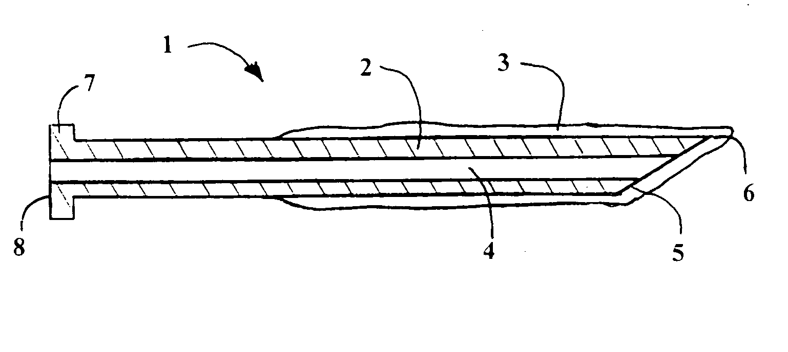
[0013]The invention is to an ice coated hypodermic needle to make an injection as painless as possible. The needle to be used is an ice coated standard needle structure. The ice coated cannula or needle 1 of a hypodermic syringe is shown in FIG. 1. A cannula shank 2 has an ice coating 3 on the front or distal or tip end 5 having a sharp needle tip and a syringe attachment or hub 7 on the proximal or rear end 8. The preferred ice coating can be from 0.010 to 0.125 inches thick.

[0014]It is known that a person suffers less or is not as sensitive to hypodermic needles where the skin or flesh surface is cold. The ice needle tip serves to cool the skin to reduce both pain and apprehension. Since the atmospheric temperature and body temperatures are both higher than the ice, as soon as the ice on the hypodermic tip end having a sharp needle tip 5 is exposed it begins to melt on its surface. The wet needle tip performs the function of assisting heat transfer from the flesh surface to the ic...


PUM


Abstract

An ice coating is placed on the hypodermic needle to cool the flesh during insertion. The ice coated front end is sharp, for penetration. The ice coating can be formed by cooling the needle and dipping it in water or molding ice onto the needle. A refrigeration chamber or cryogenic chamber can be used to cool the needle. The mold for forming an ice coating can be cooled by a cryogenic fluid or refrigerant being conducted into coils of the mold surrounding heat conducting mold walls that are used to form the ice coating on the needle. The water can be sterilized with disinfectant included.

Description

[0001]This application is a continuation-in-part of your applicant's prior patent application, Ser. No. 11 / 846166, filed Aug. 27, 2007, to an Ice Tip Hypodermic Needle.BACKGROUND OF THE INVENTION[0002]1. Field of the Invention[0003]The invention is to a frozen water coated hypodermic needle to make an injection reasonably pain free.[0004]2. Description of Related Art[0005]The use of cold surfaces and cryogenic fluids to cool the skin where injection or cutting is to take place per se is old and obvious. Examples of prior art patents that use various means to cool the skin or needle include: U.S. Pat. No. 2,536,001, issued Dec. 26, 1950, to W. Chase; U.S. Pat. No. 2,746,264, issued May 22, 1956, to F. G. Keyes; U.S. Pat. No. 3,333,587, issued Aug. 1, 1967 to R. D. Johnston; U.S. Pat. No. 3,351,063, issued Nov. 7, 1967, to Malaker et al; U.S. Pat. No. 3,399,675, issued Sep. 3, 1968, to C. W. Hill; U.S. Pat. No. 3,483,869, issued Dec. 16, 1969, to M. J. Hayhurst; U.S. Pat. No. 3,563,23...

Claims


Application Information

Patent Timeline
Patent Type & Authority Applications(United States)
IPC IPC(8): A61M5/42
CPCA61M5/329A61M2205/3606A61M5/44A61M5/422
Inventor SUN, WILLIAM Y.
Owner SUN WILLIAM Y
Why Eureka
Try Eureka