
Cartilage bore depth gauge

Inactive Publication Date: 2009-03-05
MUSCULOSKELETAL TRANSPLANT FOUND INC
View PDF6 Cites 2 Cited by
  • Summary
  • Abstract
  • Description
  • Claims
  • Application Information

AI Technical Summary

Benefits of technology

[0019]It is an object of the invention to provide a bore gauge instrument which enables a surgeon to quickly, precisely and conveniently measure the depth of bore and determine the height of surrounding area surface points of the bore.
[0022]It is yet another object of the invention to provide a bone gauge instrument which is sized for the bore diameter to be measured and which is lightweight so that a surgeon can use it with ease.

Problems solved by technology

Even though an implant with the correct diameter can be easily determined, it is difficult for the cartilage cap or top surface of the implant to align with the cartilage surface area surrounding the bore.
At present there is no known method of determining precisely how much bone or implant material should be removed from the implant plug, nor of gauging how the plug should be trimmed for correct cartilage surface alignment with the surrounding cartilage area.
Once the implant plug is seated in the bore, it is difficult to remove due to the tight interference fit with the bore walls.
Consequently, a surgeon may remove an insufficient amount of bone from the implant, creating an inadequate fit as the implant is raised above the cartilage surface or remove to much bone from the implant causing the implant upper surface to be lower than the cartilage surface, leaving the patient with an implant top surface which does not match the contour of the surrounding cartilage area.
Since the cartilage surface is a bearing surface, such raised or unequal edges of the implant can cause wear on the replacement site or present a friction area for the overlying joint surface with its adjacent hyaline cartilage surface.
However, this is a single depth measurement and does not take into consideration the differences of height taken from different positions of the cartilage surface around the periphery of the bore.
None of the prior art devices solve the problem of a non planar surface surrounding a bore cut to remove a cartilage defect in providing multiple trim measurements for an implant for the bore.

Method used


Image

  • Cartilage bore depth gauge
  • Cartilage bore depth gauge

Examples


Embodiment Construction

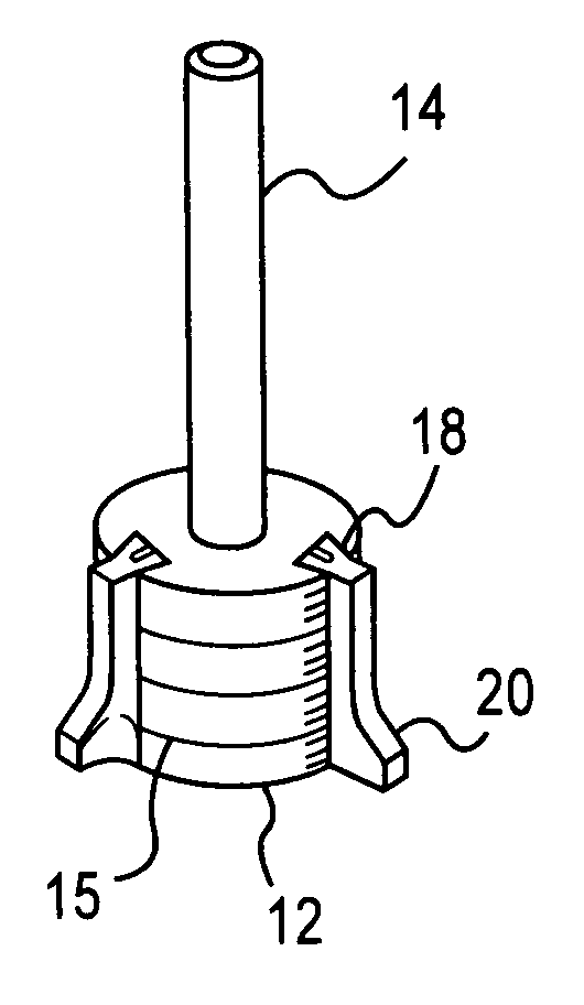
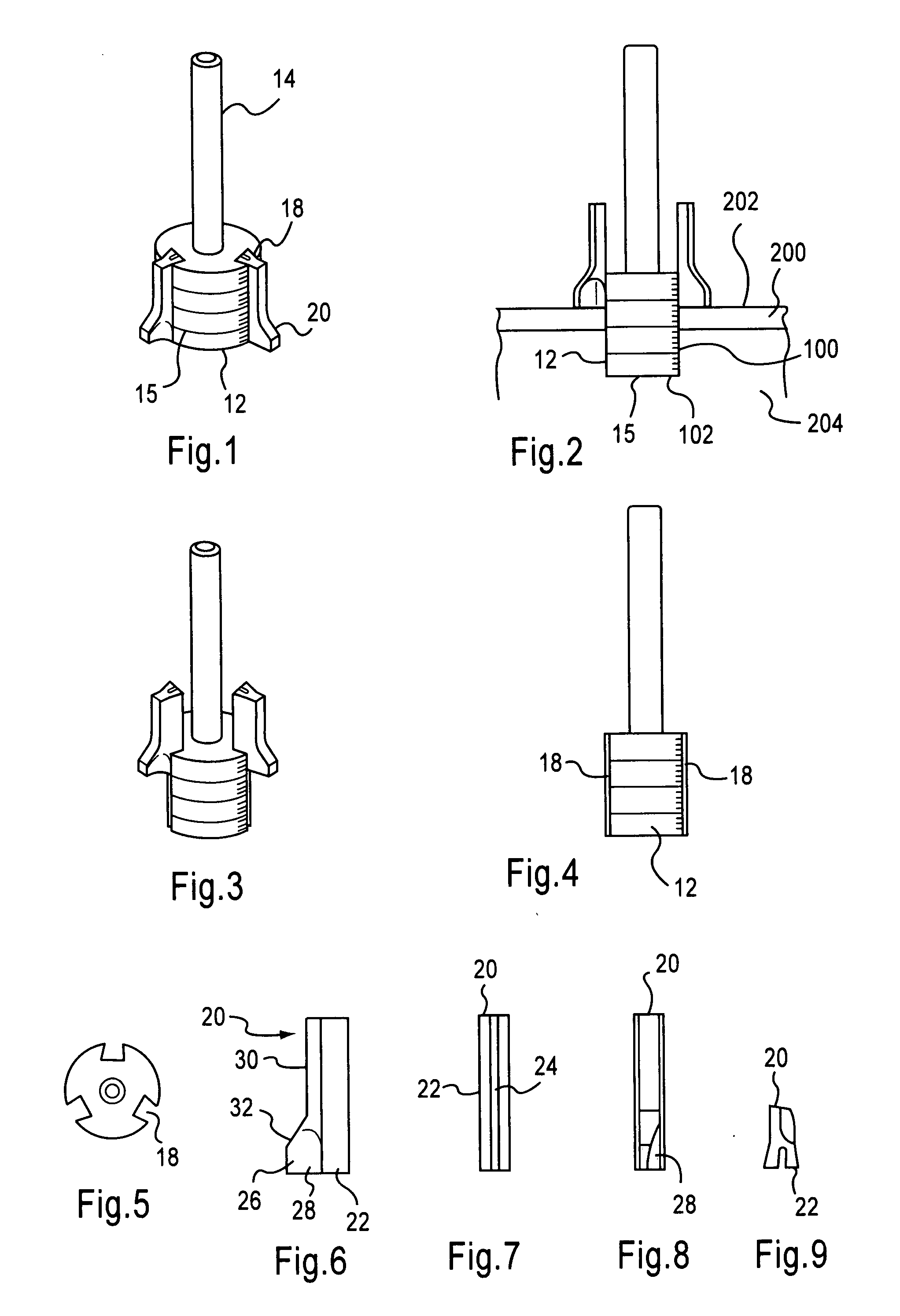
[0034]The present invention is directed towards an instrument for measuring the heights of surface areas surrounding a bore from the floor of the bore. The best mode and preferred embodiment of the invention is shown in FIGS. 1-9. The depth measuring instrument 10 is preferably constructed of surgical stainless steel. The instrument 10 has a cylindrical base member 12 having depth measurement indicia 13 marked around its circumference in millimeter increments and has an integral stem 14 extending away from the central axis of the base member 12. The stem 14 and base member 12 define a through going axial bore 16 as seen in FIG. 5 which allows the transport of blood and fluids from the bottom 102 of the cartilage defect bore 100 allowing the planar end surface 15 of the base member 12 to be seated on the bottom 102 of the bore 100. If desired, the upper section of the stem bore 16 can define a threaded portion to receive an extender member or other device. The base member 12 has a pl...


PUM


Abstract

The invention is directed toward a depth gauge instrument for simultaneously taking a number of height measurements around the surface of the area surrounding a bore from the base of the bore. The instrument has an individual cylindrical base member which has a diameter the same as the bore allowing the same to be inserted in the bore and a plurality of marker members slideably mounted in dovetail shaped grooves cut longitudinally along the outer surface of the cylindrical base member. The base member is provided with measurement indicia on its outer surface which correspond to the foot of each marker members to show the specific distance that the marker member is from the base of the bore.

Description

RELATED APPLICATIONS[0001]There is no related application.STATEMENT REGARDING FEDERALLY SPONSORED RESEARCH OR DEVELOPMENT[0002]Not applicable.REFERENCE TO SEQUENCE LISTING, A TABLE OR A COMPUTER PROGRAM LISTING COMPACT DISC APPENDIX[0003]None.BACKGROUND OF THE INVENTION[0004]1. Field of Invention[0005]The present invention is generally directed toward a device for measuring a bore depth and more particularly, a device for providing multiple measurements of the cartilage surface area surrounding a cartilage defect bore in relation to the depth of the bore.[0006]2. Background of the Invention[0007]In arthroscopic surgical procedures for alleviating a cartilage defect, it is typical to remove the defect by using a bit to remove the cartilage area and underlying subchondral bone leaving a blind bore in the defect area.[0008]Because the surface cartilage area is typically rounded, the height of the cartilage surface from the bottom of the bore taken around the periphery of the bore diffe...

Claims


Application Information

Patent Timeline
IPC IPC(8): A61B17/58B65D83/00
CPCA61B19/46A61B2019/461A61F2002/4662A61F2/30756A61B2019/462A61B90/06A61B2090/061A61B2090/062
Inventor STEINER, ANTON J.
Owner MUSCULOSKELETAL TRANSPLANT FOUND INC
Learn More