
Miniature defibrillator

a defibrillator and miniature technology, applied in the field of medical devices, can solve problems such as battery drain

Inactive Publication Date: 2009-03-05
GELBART DANIEL +1
View PDF8 Cites 2 Cited by
  • Summary
  • Abstract
  • Description
  • Claims
  • Application Information

AI Technical Summary

Problems solved by technology

A battery is keeping this capacitor charges but the leakage current causes a battery drain.

Method used


Image

  • Miniature defibrillator
  • Miniature defibrillator
  • Miniature defibrillator

Examples


Embodiment Construction

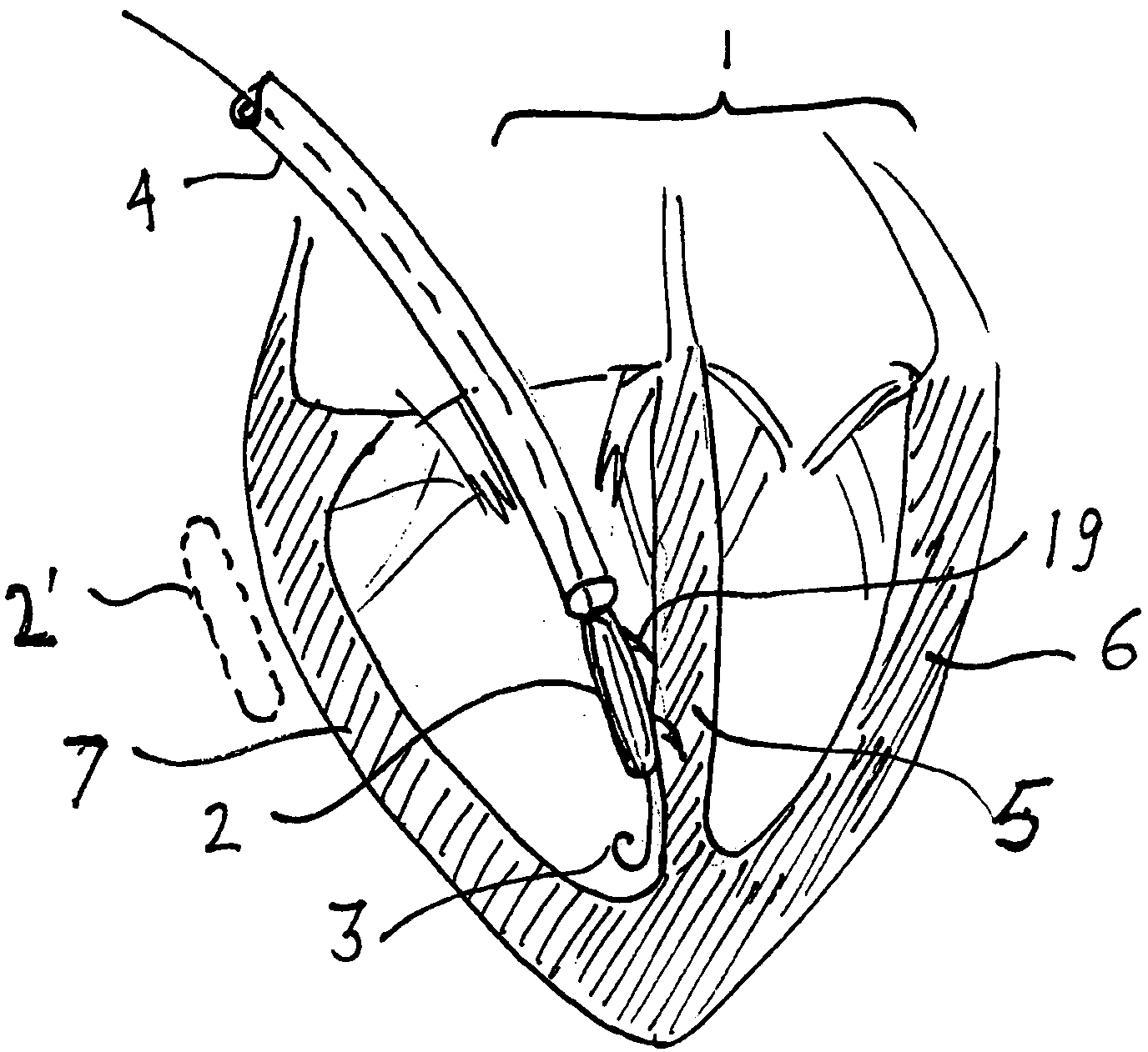
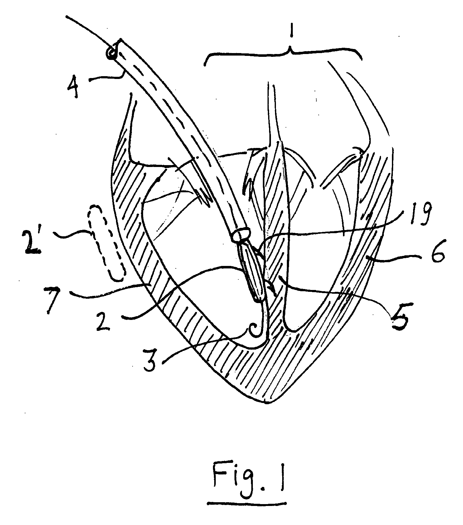
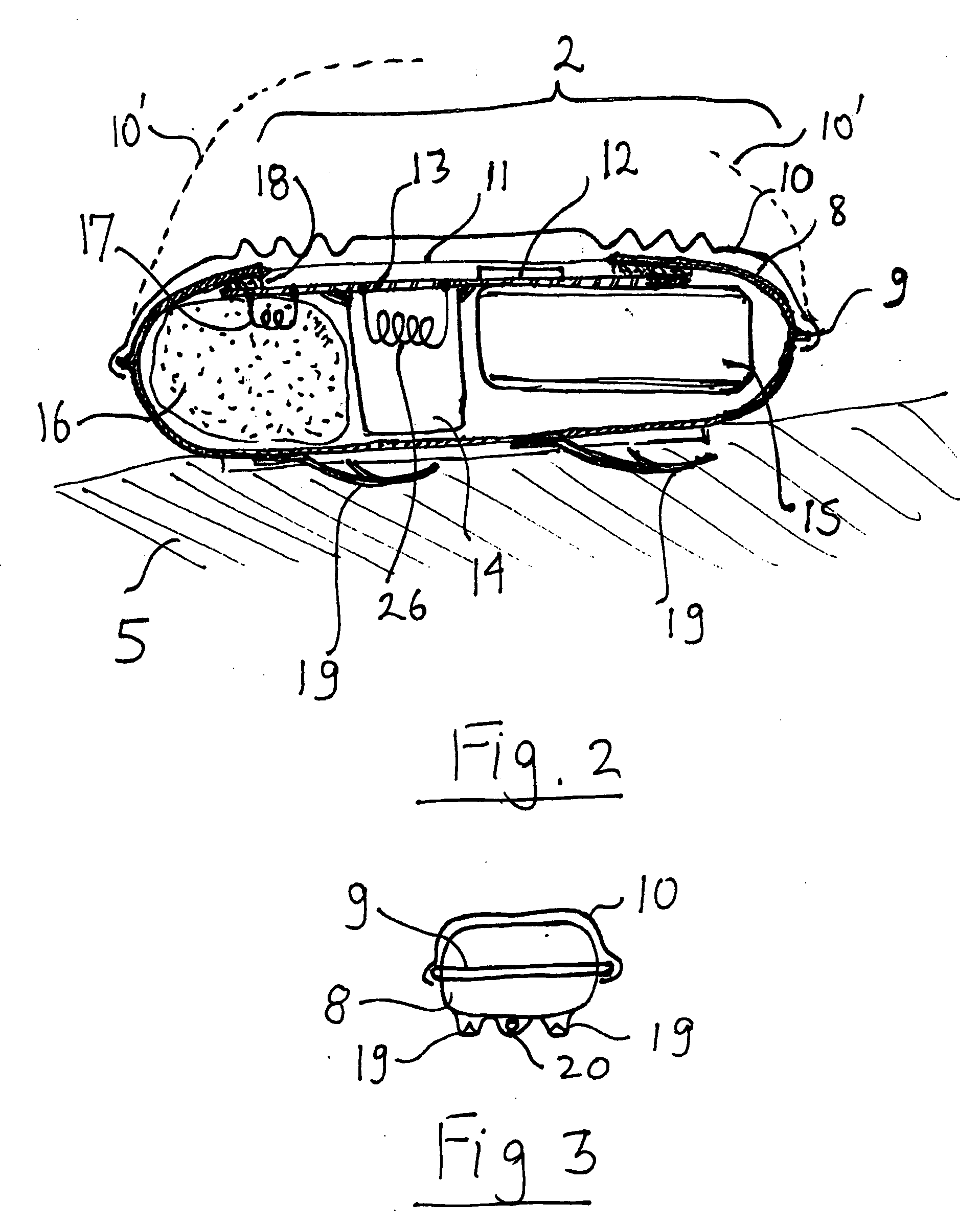
[0010]The amount of energy required to defibrillate a heart is in the range of 1 J to 200 J, depending on the exact point the energy is applied. Most defibrillators used today apply a pulse of 10 J-100 J, generated from discharging a capacitor. The volume of such a capacitor is many cubic centimeters. The same amount of energy can be supplied by an explosive charge of 10-100 mg and having a negligible volume. This allows building a defibrillator sufficiently small to be delivered percutaneously via a catheter directly into the heart. Since the principle of operation is mechanical, not electrical, no leads are required. Eliminating the leads further simplifies the process and reduces infection as well as other risks. FIG. 1 shows a miniature defibrillator 2 delivered into a heart 1 via catheter 4. A guide wire 3 can be used. The art of percutaneous delivery of cardiac implants is well known. The defibrillator 2 can be attached to the septum 6, left ventricular wall 6 or right ventric...


PUM


Abstract

A miniature implanted defibrillator ignites an explosive charge when it senses an erratic heart rhythm. The defibrillator can be delivered percutaneously into the heart or can be implanted in the vicinity of the heart via minimally invasive surgery. The shock created by the exploding charge defibrillates the heart. Single use and multiple use devices are possible. The same principle can be used for a disposable external defibrillators.

Description

FIELD OF THE INVENTION[0001]The invention is in the medical field and more specifically is related to implantable cardiac defibrillatorsBACKGROUND OF THE INVENTION[0002]Defibrillators are used to re-start the heart in case of erratic rhythm (fibrillation) or cessation of pacing. There are two types of defibrillators: external and internal (implanted). Since the energy required to shock the heart and re-start it is in the range of tens of Joules, the implanted defibrillators rely on a large energy storage capacitor. A battery is keeping this capacitor charges but the leakage current causes a battery drain. The size of capacitor and battery requires implantation by surgery. It is desirable to have a defibrillator sufficiently small to be delivered percutaneously via a catheter. Since defibrillators can be viewed as a preventive measure, and many of the installed ones are never activated, more would be used if the installation was simpler. It is also desirable to have a device with ver...

Claims


Application Information

Patent Timeline
IPC IPC(8): A61N1/39
CPCA61H31/004A61N1/39A61H2201/5097A61H31/006
Inventor GELBART, DANIELLICHTENSTEIN, SAMUEL VICTOR
Owner GELBART DANIEL
Learn More