Method and System for Controlling a Well Service Rig Based on Load Data

a technology of load data and service rig, which is applied in the direction of survey, wellbore/well accessories, hoisting equipment, etc., can solve the problems of reduced safety chances caused by tubing or rod hanging or getting caught in the wellbore, increased time, and reduced speed of the block or hoist, so as to improve the ability to prevent damage to the service rig and injury to the workers around the well head. , the effect of increasing the reaction tim

Active Publication Date: 2009-03-05
KEY ENERGY SERVICES
View PDF11 Cites 20 Cited by
  • Summary
  • Abstract
  • Description
  • Claims
  • Application Information

AI Technical Summary

Benefits of technology

[0008]The present invention is directed to controlling the operation of a well service rig based on rig load data. By removing the need for or limiting the capabilities of the operator during situations of increased load on the well service rig the ability to prevent damage to the service rig and injury to the workers around the well head can be improved. Furthermore, by limiting the speed of the well service rig during periods where only a small amount of tubing or rods remains to be pulled out of a wellbore, the opportunity for a dangerous situation caused by the tubing or rod hanging or getting caught up in the wellbore is reduced based on the fact that reaction time is increased at the slower speeds.
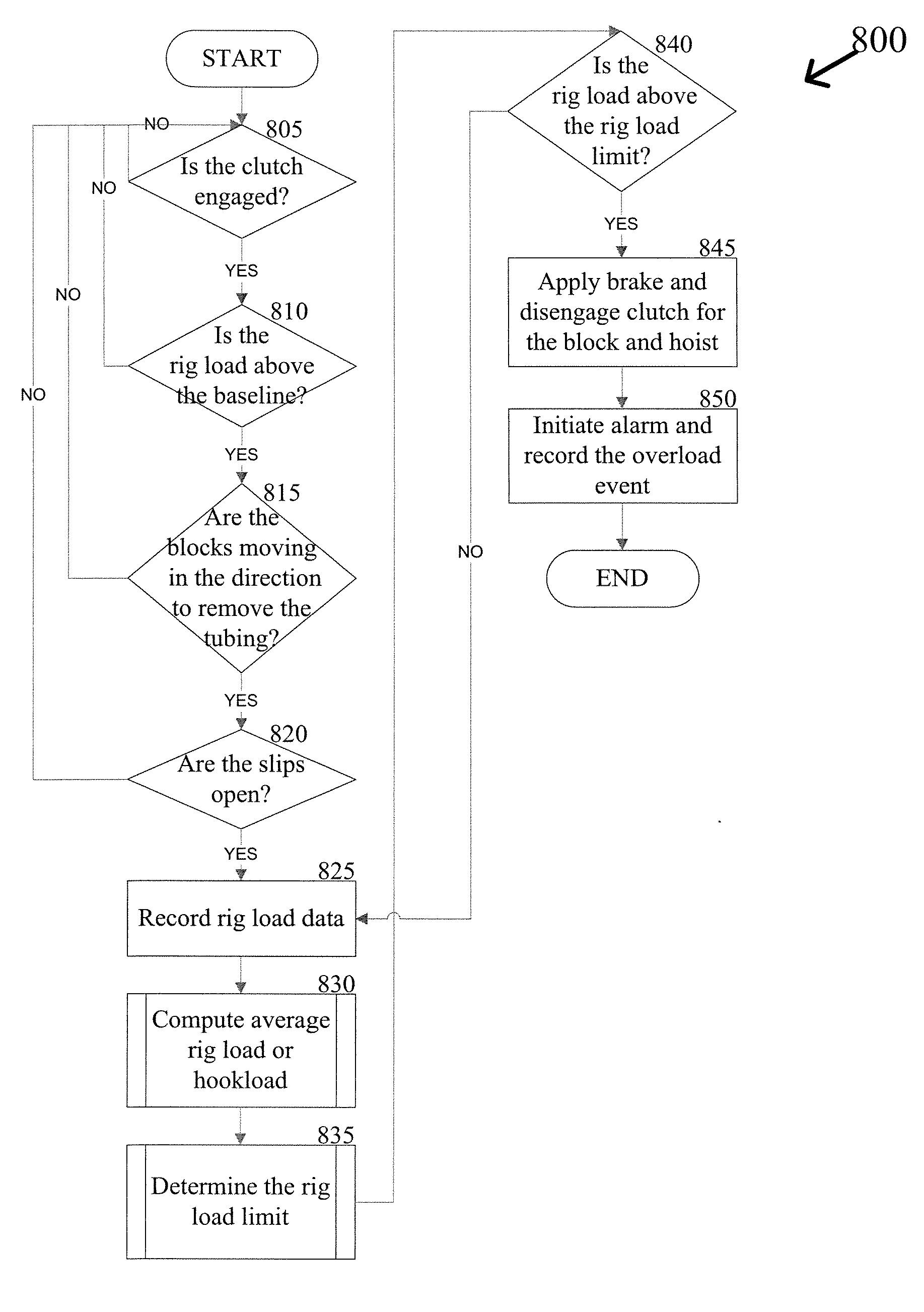
[0010]For another aspect of the present invention, a method for determining when to reduce or limit block and / or hoist speed during a pulling operation can be achieved based on an evaluation of hook load data. Load data can be received from sensors on the well service rig related to load calculations taken during the removal of a pipe string from a well. The hookload or rig load can be calculated based on the load data. An evaluation of the hookload or rig load can be conducted to determine if the load has fallen to or below a certain level. That level can be indicative that the weight of the remaining pipe string in the well is much less than when the pull operation first began. If the load is below a certain level, the speed of the block or the hoist can be limited to an speed that is substantially slower than the normal operation of the block and hoist during a standard pulling operation. The reduced speed can increase reaction time in case the pipe string becomes caught in the well.
[0011]For still another aspect of the present invention, a method for preventing a well service rig from pulling a stand of pipe away from a pipe string while the stand of pipe is still engaged with the threads of the pipe string can be achieved based on an evaluation of rig load or hookload data. The system can receive information indicating that the rig is disengaging a stand of pipe from a pipe string, such as through the use of tongs. Load data, such as rig load or hookload data can be received when the stand of pipe is being disengaged from the pipe string. An evaluation of the load data can be conducted to determine if the load data has increased above a certain level that is indicative of a stand of pipe being pulled up before the de-threading process has occurred from the pipe string. If the load level has increased to or above a certain level, the clutch for the drive system that is raising the stand of pipe can be disengaged automatically or the throttle can be reduced to prohibit over pulling.

Problems solved by technology

Furthermore, by limiting the speed of the well service rig during periods where only a small amount of tubing or rods remains to be pulled out of a wellbore, the opportunity for a dangerous situation caused by the tubing or rod hanging or getting caught up in the wellbore is reduced based on the fact that reaction time is increased at the slower speeds.
If the load is below a certain level, the speed of the block or the hoist can be limited to an speed that is substantially slower than the normal operation of the block and hoist during a standard pulling operation.

Method used


Image

  • Method and System for Controlling a Well Service Rig Based on Load Data
  • Method and System for Controlling a Well Service Rig Based on Load Data
  • Method and System for Controlling a Well Service Rig Based on Load Data

Examples


Embodiment Construction

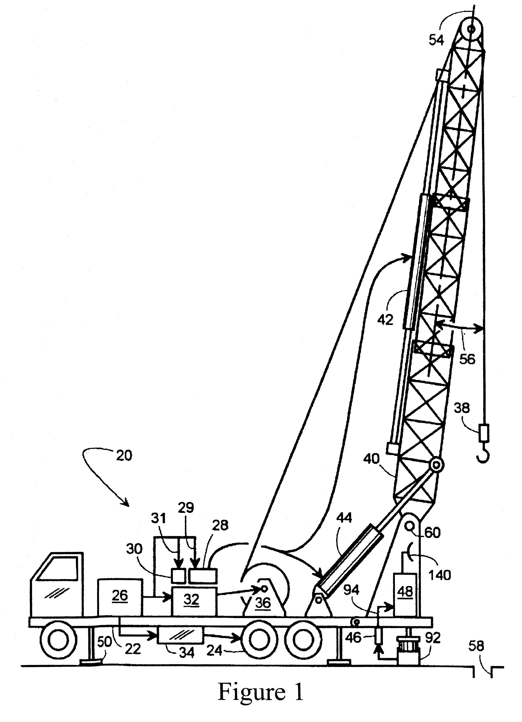
[0028]Exemplary embodiments of the invention will now be described in detail with reference to the included figures. The exemplary embodiments are described in reference to how they might be implemented. In the interest of clarity, not all features of an actual implementation are described in this specification. Those of ordinary skill in the art will appreciate that in the development of an actual embodiment, several implementation-specific decisions must be made to achieve the inventors' specific goals, such as compliance with system-related and business-related constraints which can vary from one implementation to another. Moreover, it will be appreciated that such a development effort might be complex and time-consuming, but would nevertheless be a routine undertaking for those of ordinary skill in the art having benefit of this disclosure. Further aspects and advantages of the various figures of the invention will become apparent from consideration of the following description ...


PUM


Abstract

The present invention is directed to methods for controlling the operations of a well service rig at a well site by evaluating load sensor data obtained from sensors on or associated with the well service rig. A rig load data chart can be reviewed and an average rig load can be determined for each pull of tubing or rods from a well. The average rig load can be used to calculate and set a rig overload level. If the rig load sensor reads a rig load at or above the rig overload level, the clutch for the hoist can be disengaged and the brake applied to prevent the load from either damaging the rig or breaking off the tubing or rods in the well. In addition, the rig load can be evaluated to determine when the limit the block speed when pulling rods or tubing.

Description

FIELD OF THE INVENTION[0001]The present invention generally pertains to equipment used for repairing wells that have already been drilled. More specifically the present invention pertains to an analysis of rig loads and rig load data to determine and monitor tubing and / or rod removal overload conditions on a well service rig.BACKGROUND OF THE INVENTION[0002]After a well has been drilled, it must be completed before it can produce gas or oil. Once completed, a variety of events may occur to the formation causing the well and its equipment to require a “work-over.” For purposes of this application, “work-over” and “service” operations are used in their very broadest sense to refer to any and all activities performed on or for a well to repair or rehabilitate the well, and also includes activities to shut in or cap the well. Generally, work-over operations include such things as replacing worn or damaged parts (e.g., a pump, sucker rods, tubing, and packer glands), applying secondary o...

Claims


Application Information

Patent Timeline
Patent Type & Authority Applications(United States)
IPC IPC(8): G01V1/40E21B47/00
CPCE21B19/00
Inventor NEWMAN, FREDERIC M.
Owner KEY ENERGY SERVICES
Why Eureka
Try Eureka