Threading device of sewing machine

a technology of threading device and sewing machine, which is applied in the direction of sewing apparatus, loop holders, textiles and paper, etc., can solve the problems of either or both of the threading device and the spreader breaking, and achieve the effect of preventing them from breaking

Inactive Publication Date: 2009-03-12
JUKI CORP
View PDF6 Cites 7 Cited by
  • Summary
  • Abstract
  • Description
  • Claims
  • Application Information

AI Technical Summary

Benefits of technology

[0007]It is an object of the present invention to provide a threading device of a sewing machine, which can prevent a collision between the threading device and a spreader to prevent them from breaking.

Problems solved by technology

However, there has been a problem that, when the operator operates the threading device by mistake while the spreader is attached, the threading device collides with the spreader, resulting in breakage of either or both of the threading device and the spreader.

Method used


Image

  • Threading device of sewing machine
  • Threading device of sewing machine
  • Threading device of sewing machine

Examples


first embodiment

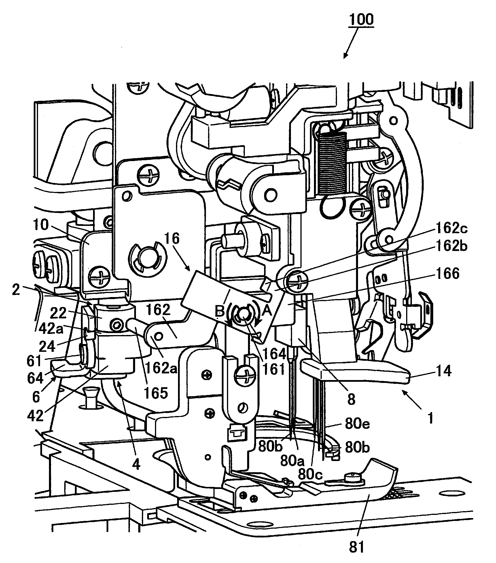
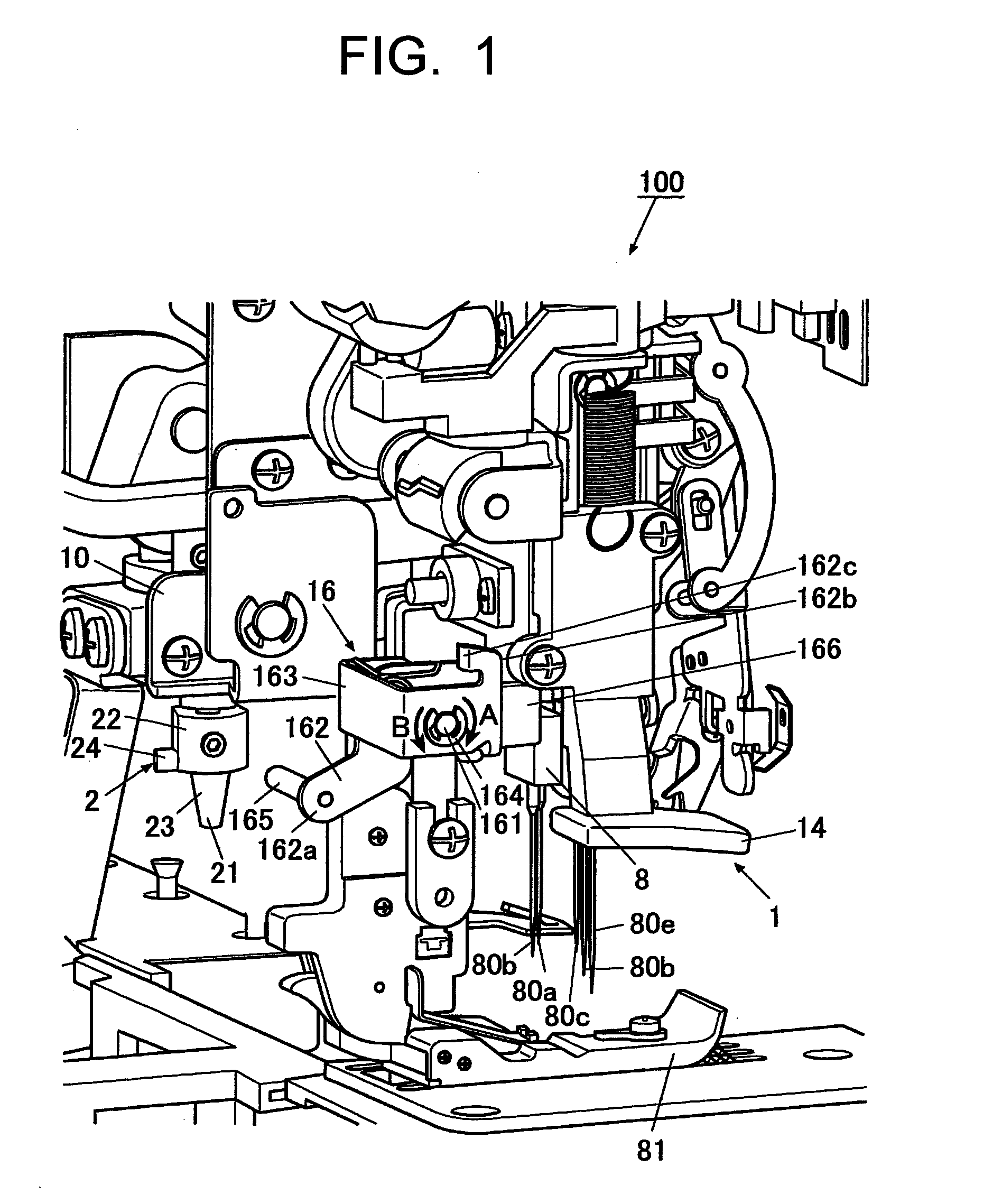
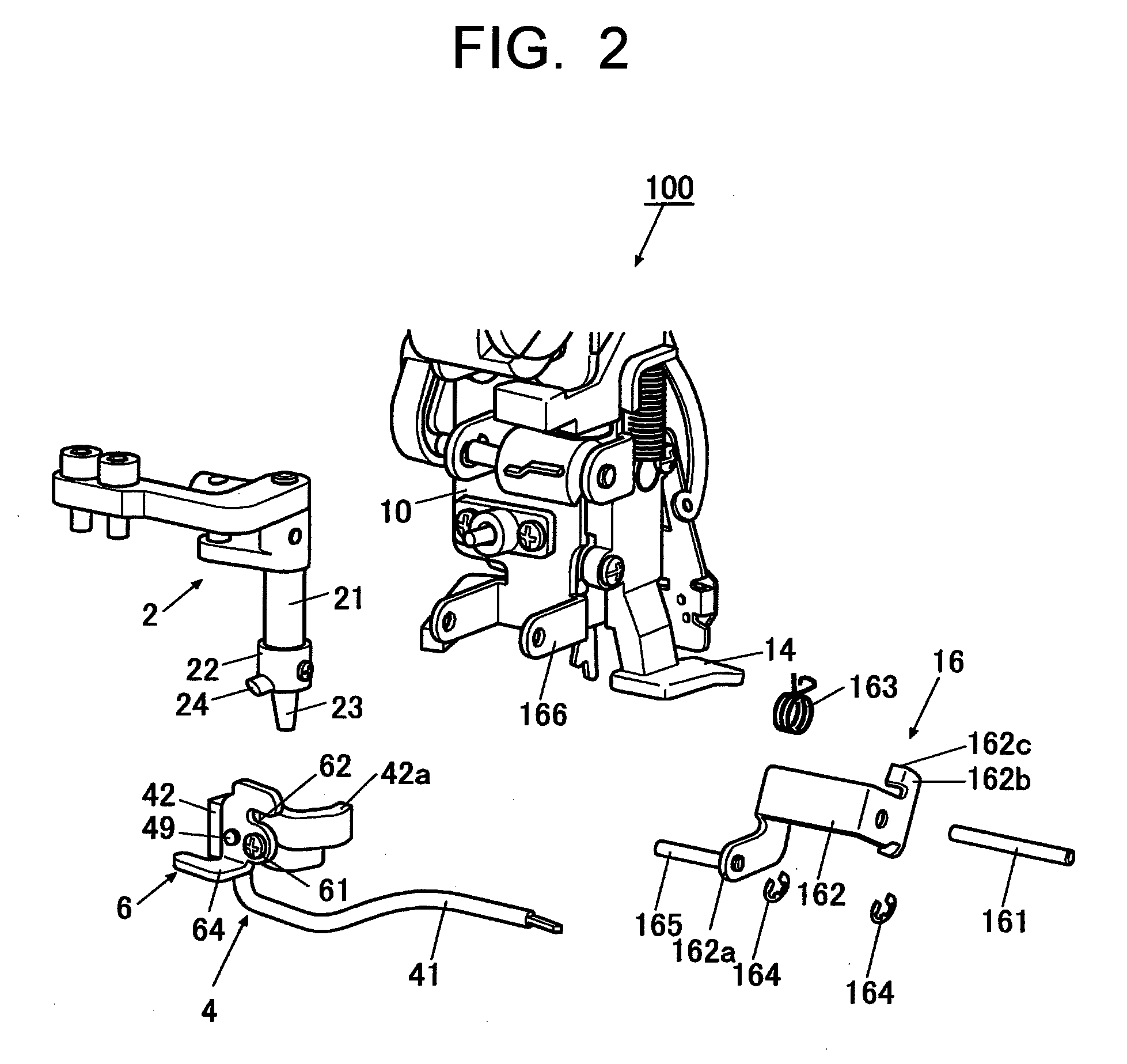
[0023]As shown in FIGS. 1 to 5, a threading device 1 according to a first embodiment of the present invention is provided near a jaw portion of a sewing machine 100. The threading device 1 inserts needle threads (stitching threads) through eyes of needles below the jaw portion. The sewing machine 100 equipped with the threading device 1 can implement both overlock stitching and cover stitching sewing with a single machine. The sewing machine 100 includes five needles 80a, 80b, 80c, 80d, 80e which are arranged in lines. Each of the needles 80a to 80e are held by a single needle bar 8, and is moved up and down by driving a sewing machine motor to insert the respective needle threads through a workpiece.

[0024]As shown in FIG. 4, in the following description, a direction parallel to the longitudinal direction of the needles 80a to 80e is defined as a Z-axis direction, a direction orthogonal to the longitudinal direction of the needles 80a to 80e and along which the needles 80a to 80e ar...

second embodiment

[0087]Next, a threading device of a sewing machine according to a second embodiment of the present invention will be described. Components similar to those in the first embodiment are indicated by the same reference numerals, and description thereof will be omitted. FIG. 9 is a block diagram of the threading device 1a of the second embodiment.

[0088]A control device 200 includes the threading device 1a of the sewing machine. A sensor 201 is coupled to the control device 200, and detects that the spreader mechanism 4 is attached to the top covering shaft mechanism 2. The sensor 201 is provided on the top covering shaft mechanism 2, and when it detects that the spreader mechanism 4 is attached to the top covering shaft mechanism 2, it transmits a detection signal to the control device 200.

[0089]A solenoid 202, from which a plunger moves in and out of the movement path of the operation lever 14, is coupled to the control device 200. The solenoid 202 is provided on the sewing machine mai...

third embodiment

[0094]Next, a threading device of a sewing machine according to a third embodiment of the present invention will be described. Components similar to those in the first embodiment are indicated by the same reference numerals, and description thereof will be omitted. FIG. 10 is a block diagram of the threading device 1b of the third embodiment.

[0095]The threading device 1b includes a control device 300. A sensor 301 is coupled to the control device 300, and detects that the spreader 4 is attached to the top covering shaft mechanism 2. The sensor 301 is provided on the top covering shaft mechanism 2, and when it detects that the spreader mechanism 4 is attached to the top covering shaft mechanism 2, it transmits a detection signal to the control device 300.

[0096]A solenoid 302 is coupled to the control device 300, and actuates a clutch mechanism provided between the operation lever 14 and the threading operation mechanism 13. The solenoid 302 is driven in response to a drive command si...


PUM


Abstract

A threading device of a sewing machine is provided. The threading device includes a threading hook which moves forward to enter an eye of a needle to catch a needle thread, and moves rearward with the needle thread being caught to insert the needle thread through the eye, a threading shaft which holds the threading hook, an operating member which is operated to move the threading shaft, a threading operation mechanism which transmits the movement of the threading shaft to the threading hook to move the threading hook back and forth, and a restricting device which makes the threading operation mechanism inoperable when the spreader mechanism is attached to the sewing machine main body, and makes the threading operation mechanism operable when the spreader mechanism is detached from the sewing machine main body.

Description

CROSS-REFERENCE TO RELATED APPLICATION[0001]The present application claims priority from Japanese Patent Application No. 2007-236739 filed on Sep. 12, 2007, the entire content of which is incorporated herein by reference.FIELD OF INVENTION[0002]The present invention relates to a threading device of a sewing machine which has a plurality of needles and can form covering stitches.DESCRIPTION OF RELATED ART[0003]A related art sewing machine is configured to form covering stitches on a workpiece. The sewing machine includes a plurality of needles arranged in a direction intersecting with a direction in which the workpiece is to be fed, a spreader which arcuately moves from a side to a front of the needles above the workpiece, and a looper which rotates below a throat plate on which the workpiece is placed. The plurality of needles moves up and down with needle threads being inserted therethrough, respectively. The spreader arcuately moves in synchronization with the up and down movement...

Claims


Application Information

Patent Timeline
Patent Type & Authority Applications(United States)
IPC IPC(8): D05B87/02
CPCD05B87/02
Inventor MIYOSHI, TAKANAO
Owner JUKI CORP
Why Eureka
Try Eureka