Double Break Disconnect/Contact System

a contact system and double break technology, applied in the direction of circuit breaking switches, circuit breaking switches for excess current, snap-action arrangements, etc., can solve the problems of significant hysteresis, contact force between fixed and moveable contacts in the on position to be compromised, and the functional performance of such conventional mechanisms is typically affected, so as to reduce or eliminate friction, reduce or eliminate hysteresis and mechanism performance dependency, and ensure the effect of stability

Active Publication Date: 2009-03-12
SIEMENS IND INC
View PDF12 Cites 21 Cited by
  • Summary
  • Abstract
  • Description
  • Claims
  • Application Information

AI Technical Summary

Benefits of technology

[0017]Still yet another purpose of this invention is to provide a reliable locking of a contact arm in a blow-off position by using surfaces of either locking blocks/protrusions or a locking plate that are integral with or fastened to a crossbar module.
[0018]And yet another purpose of this invention is to reduce or even eliminate friction between the contact mechanism components, such as sliding pins and the Crossbar ...

Problems solved by technology

Functional performance of such conventional mechanisms is typically affected by the friction between a rolling or a sliding component, which moves with the contact arm, and the intermediate cam surfaces along the entire trajectory.
This results in a significant hysteresis, which is undesirable for the contact system as it brings inconsistency and can cause the contact force between the fixed and moveable contacts in the ON position to be compromised.
Furthermore, using the intermediate cam to achieve required torque at the contact arm in the ON position has a negative effect on the mechanism's over-travel performance an...

Method used


Image

  • Double Break Disconnect/Contact System
  • Double Break Disconnect/Contact System
  • Double Break Disconnect/Contact System

Examples


first embodiment

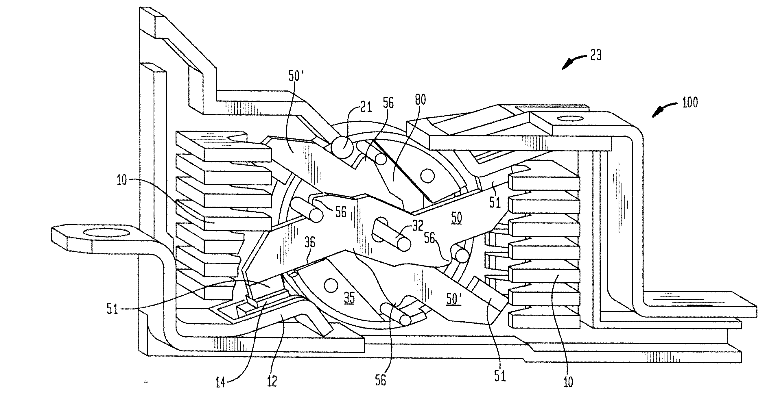
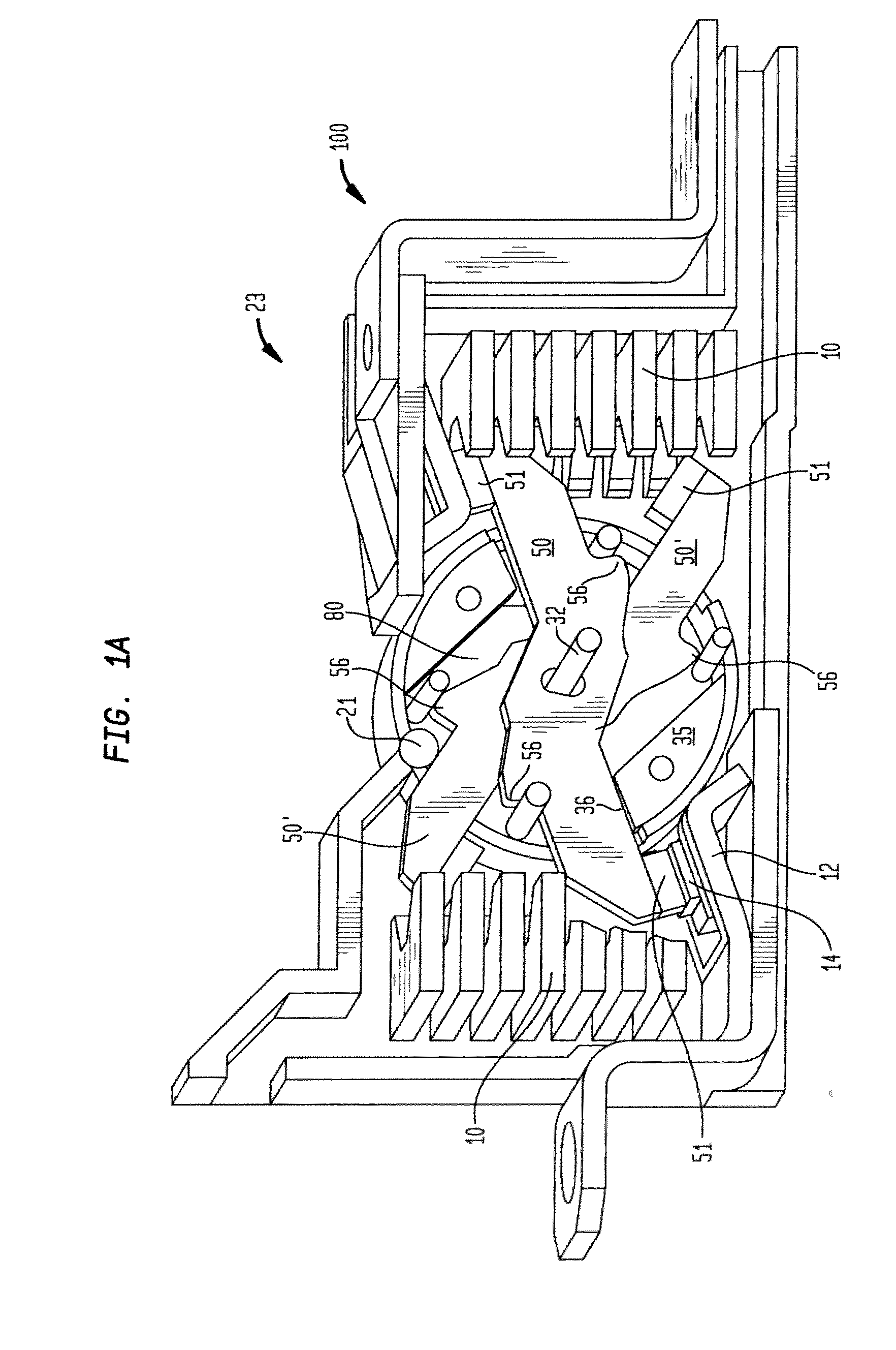
[0043]FIG. 1A is a perspective view of the inventive contact mechanism assembly for a circuit breaker 23, illustrating the present invention showing the contact mechanism inside a cassette housing 100, with a contact arm 50, in an ON position 50, and then in a blow-off position 50′.

[0044]FIG. 1B is a perspective view of the inventive contact mechanism assembly for a circuit breaker 23, illustrating a first embodiment of the present invention showing the contact mechanism and the contact arm 50, in the ON position 50.

[0045]FIG. 2A is a perspective detailed view of one half of the crossbar module 80, of the inventive contact mechanism assembly for a circuit breaker 23, illustrated in FIG. 1.

[0046]FIG. 2B is a perspective detailed view of both halves of the crossbar module 80 or of a crossbar module 80 made of one piece, of the inventive contact mechanism assembly for a circuit breaker 23, illustrated in FIG. 1.

[0047]FIG. 2C is a perspective detailed view of one half of the crossbar mo...

second embodiment

[0054]FIG. 5B is an enlarged detailed view showing a contact arm 150, that can be used with this invention.

[0055]Now referring to FIGS. 1A through 5B, the inventive contact mechanism assembly for a circuit breaker 23, comprises an arc extinguishing mechanism 10, a pair of fixed contact assemblies 12, each having a fixed contact pad 14. A contact arm assembly 50, having a movable contact 51, a contact arm body 58, contact arm edge-surfaces 59, a bump or notch or hook or structural stop 56, and a slotted hole or opening 60, which encompasses a central pivot axle 32, which is fixed / secured to the crossbar module 80. The contact arm assembly 50 is flexibly connected to the crossbar module 80 using either one or two pairs of springs, namely, a first spring 45, and a second spring 55, such that one end of the first spring 45, is secured to a fixed pin or anchor 42, which is secured to the crossbar module 80, and the other end of the first spring 45, is secured to a sliding pin 54, which i...

third embodiment

[0076]FIG. 8 is a side view of the inventive contact mechanism assembly for a circuit breaker 323, illustrating the present invention showing the contact arm 350, in an ON-position 350, and then in a blow-off position 350′.

[0077]FIG. 9 is a top view of the inventive contact mechanism assembly for a circuit breaker 323, illustrated in FIG. 8.

[0078]Now referring to FIG. 8, and FIG. 9, the crossbar module 380, central pivot axle 332, moveable contacts 351, and fixed contact assemblies 12, two sliding pins or rollers 352, 354, and two anchor pins 342, 344, are correspondingly identical to those described for the preferred embodiment of FIGS. 1A through 5B.

[0079]A split contact arm assembly 350, identical to the one described for the second embodiment described in FIGS. 6 and 7.

[0080]The split version of the contact arm 350, which consists of two symmetrical formed halves, that are secured together, such as, by brazing or welding or by other methods, to form a contact arm assembly 350, w...


PUM


Abstract

The present invention relates generally to a mechanism of a contact system for circuit breakers. More particularly, the invention encompasses a mechanism for a rotary double-break contact system, which enables a direct transfer of torque from stored energy components, such as, springs, to the contact arm in the ON-position (contacts closed) without using intermediate cam surface. The mechanism described in the invention also ensures reliable locking of the contact arm in the blow-off position using stationary means that are integral with or fixed to a crossbar module. This invention enables to achieve significant reduction or even to eliminate friction at certain critical interfaces between the contact mechanism components, thus, reducing or potentially eliminating hysteresis, and improving performance consistency, and also eliminating mechanism performance dependency on wear level and condition of an intermediate cam surface. An additional feature of this invention is a reduction of a loss of contact torque/force during over-travel in the ON position when the fixed and/or moveable contacts erode. Configurations described in this invention may also feature physical protection for the moving components of the contact mechanism assembly from flying particles resulting from short circuit shots.

Description

CROSS-REFERENCE TO RELATED APPLICATION[0001]The instant patent application is related to U.S. Provisional Patent Application Ser. No. 60 / 971,332, filed on Sep. 11, 2007, titled “Double-Break Disconnect / Contact System,” U.S. Provisional Patent Application Ser. No. 60 / 971,340, filed on Sep. 11, 2007, titled “Rotary Double-Break Contact System Mechanism Directly Creating Contact Torque in the ON position and Locking Contact Arm in the Blow-Off Position,” U.S. Provisional Patent Application Ser. No. 60 / 971,345, filed on Sep. 11, 2007, titled “Double-Break Contact System,” and, U.S. Provisional Patent Application Ser. No. 60 / 971,350, filed on Sep. 11, 2007, titled “Double-Break Circuit Breaker Mechanism,” the disclosures of which is incorporated herein by reference.FIELD OF THE INVENTION[0002]The present invention relates generally to a mechanism of a contact system for circuit breakers. More particularly, the invention encompasses a mechanism for a rotary double-break contact system, wh...

Claims


Application Information

Patent Timeline
IPC IPC(8): H01H5/06
CPCH01H77/104H01H1/205
Inventor SHMUKLER, MARK I.FERREE, JAMES
Owner SIEMENS IND INC
Why Eureka
Try Eureka