Eletrofluid collisional accelerator and fusion reactor

a technology of electrofluid and collision accelerator, which is applied in the field of electrofluid fusion systems, can solve the problems of operator receiving a severe electrostatic shock

Inactive Publication Date: 2009-03-12
KEADY JOHN P
View PDF6 Cites 37 Cited by
  • Summary
  • Abstract
  • Description
  • Claims
  • Application Information

AI Technical Summary

Problems solved by technology

However, they are typically not discussing a true charged fluid (e.g., charged molten metal or charged water with impurities).
On any ungrounded surfaces, charges will build up and any contact with an operator will ground out these surfaces, and thus the operator may receive a severe electrostatic shock.
Because the level of thrust from a single spray element is inevitably small, it is very likely that any one vehicle can require a multiplicity of spray elements to provide the variability in magnitude and direction of thrust that may be required.
In conventional fusion systems the density is either to low, or the temperature not high enough, or the confinement time not high enough.

Method used


Image

  • Eletrofluid collisional accelerator and fusion reactor
  • Eletrofluid collisional accelerator and fusion reactor
  • Eletrofluid collisional accelerator and fusion reactor

Examples


first exemplary embodiment

[0127]The first exemplary embodiment is directed toward accelerating charged hydrogenated fluid into collisions of sufficient energy to initiate at least partial fusion of the collisional hydrogenated fluid, where one of the products of the collision is a product including an element higher in the periodic tables than at least one of the collided fluids, and where, optionally, the at least partial fusion heats a coolant loop which in turn generates electricity.

second exemplary embodiment

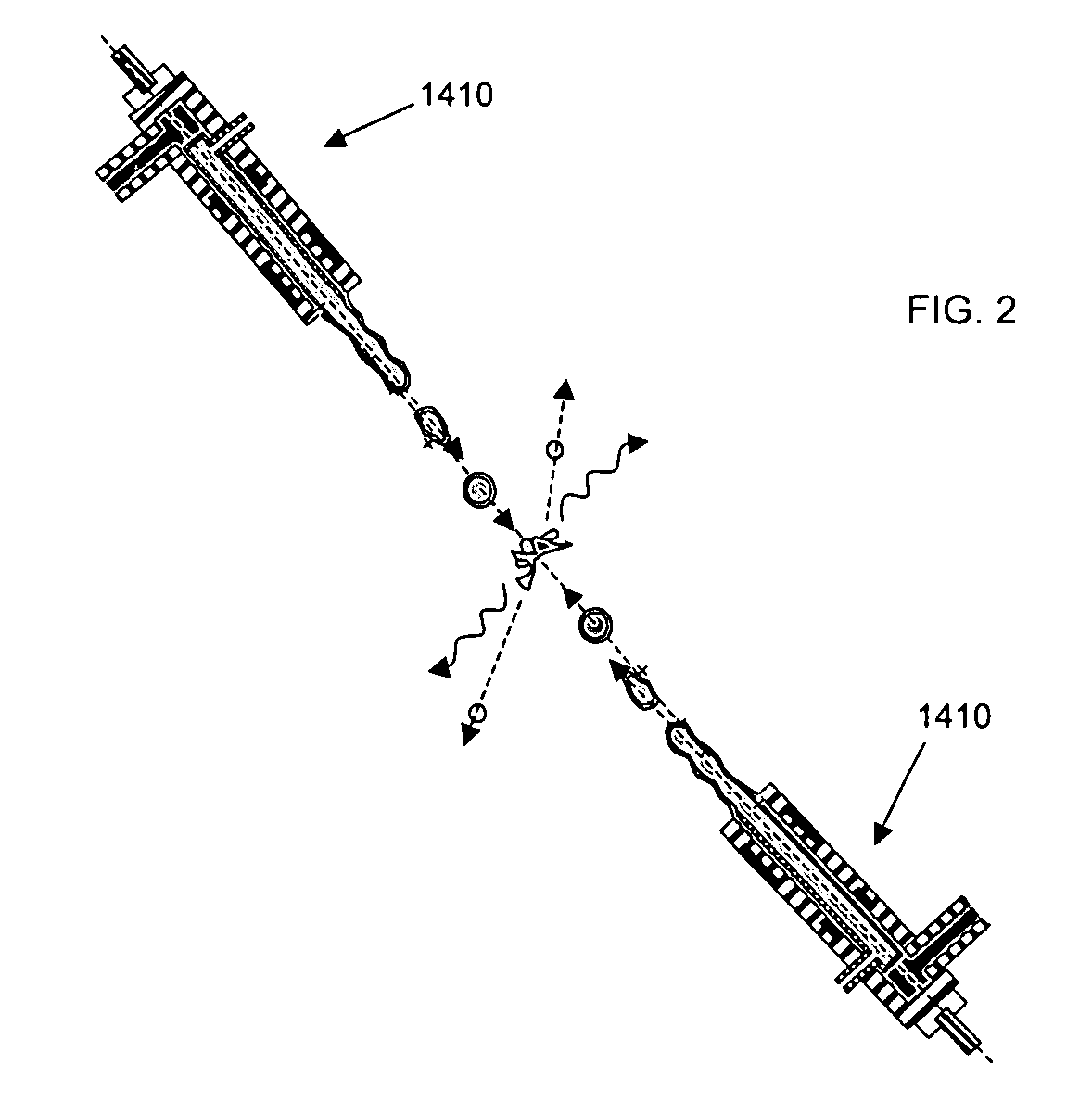
[0128]The second exemplary embodiment is directed to the collisional fusion of at least two oppositely charged hydrogenated fluid streams, droplets, and / or mists.

third exemplary embodiment

[0129]The third exemplary embodiment is directed to the collisional fusion of at least two neutralized charged fluid streams, droplets, and / or mists.


PUM


Abstract

At least one exemplary embodiment is directed toward accelerating charged hydrogenated fluid into collisions of sufficient energy to initiate at least partial fusion of the collisional hydrogenated fluid, where one of the products of the collision is a product including an element higher in the periodic tables than at least one of the colliding fluids, and where, optionally, the at least partial fusion heats a coolant loop which in turn generates electricity.

Description

CROSS-REFERENCE TO RELATED APPLICATIONS[0001]This application claims a priority benefit of U.S. provisional patent application 60 / 868,074 filed on 30 Nov. 2006, incorporated herein by reference in it's entirety.FIELD OF THE INVENTION[0002]The invention relates in general to devices and methods of electrofluid technology, and particularly though not exclusively, is related to electrofluid fusion systems.BACKGROUND OF THE INVENTION[0003]In 1988 Dr. Keady developed one of the first co-axial electrofluid devices, which charged droplets of water and kerosene, and deflected the droplets in an electric field. Electrified fluid can impact many future industries, propulsion, detector designs, manufacturing, optics, power generation and transfer, shielding, nanotechnology, and semiconductor structure formation, to mention just a few. The system was described at a NASA Langley conference in 1988 as a student paper and presentation.Charged Fluid Technology[0004]Plasma physicist sometimes refer ...

Claims


Application Information

Patent Timeline
Patent Type & Authority Applications(United States)
IPC IPC(8): G01J1/00
CPCG21B1/15Y02E30/16G21B1/19Y02E30/10
Inventor KEADY, JOHN P.
Owner KEADY JOHN P
Why Eureka
Try Eureka