Paper transport apparatus

a technology of paper transport and squeezing mechanism, which is applied in the direction of feed tables, thin material processing, article separation, etc., can solve the problems of affecting the quality of paper, so as to prevent smudges on the surface of the sheet, easy inverting, and eliminating ink stain

Active Publication Date: 2009-03-12
SEIKO EPSON CORP +1
View PDF8 Cites 6 Cited by
  • Summary
  • Abstract
  • Description
  • Claims
  • Application Information

AI Technical Summary

Benefits of technology

[0015]As described above, according to the present invention, a sheet is inverted around the inversion axis at the turn guide while being transported from the first transport surface of the first transport apparatus to the second transport surface of the second transport apparatus through the inversion / transfer surfaces of the turn guide. At this point, the printed surface of the sheet does not come into contact with the constituent members of an inversion device. Thus it is possible to eliminate an ink stain and prevent smudges on a surface of the sheet.
[0016]As the inversion / transfer surfaces of the guide ribs have a larger curvature radius, a thick sheet can be easily inverted and it becomes difficult to invert a sheet having a short length in the transport direction, whereas as the inversion / transfer surfaces have a smaller curvature radius, it becomes difficult to invert a thick sheet and a sheet having a short length in the transport direction can be easily inverted.
[0017]Therefore, the guide rib groups can move between the operation position where the guide rib groups are connected to the first transport surface and the second transport surface so as to guide the sheet and the retraction position where the guide rib groups are separated from the first transport surface and the second transport surface so as not to guide the sheet, and the guide rib group having the optimum curvature radius for the size and thickness of the sheet to be transported is disposed on the operation position, so that the sheet can be smoothly inverted.

Problems solved by technology

Further, in a configuration for sucking a sheet of paper on a transport belt, the transport belt itself cannot form a curved inversion path.
However, it is difficult to provide the turn guide with a sucking function and thus a suction force is not applied to a sheet of paper at the turn guide while the sheet is moved from one transport apparatus to another.
Thus when a transport force is applied to the sheet at the front and rear of the turn guide, particularly cardboard having high stiffness has a large transport resistance at the turn guide, increasing the possibility that an insufficient transport force may cause faulty transport.
Further, when the sheet is forcibly transported, the sheet may be curled or may be sharply bent in the worst case.

Method used


Image

  • Paper transport apparatus
  • Paper transport apparatus
  • Paper transport apparatus

Examples


Embodiment Construction

[0050]Embodiments of the present invention will now be described in accordance with the accompanying drawings. First, referring to FIGS. 24 to 28, the following will discuss an application of a paper transport apparatus and a paper transport path according to the present invention.

[0051]As shown in FIGS. 24 and 25, an inkjet printer will be illustrated as an application of the paper transport apparatus of the present invention. The present invention is also applicable to a stencil duplicator, a screen printer, and so on.

(overall Configuration)

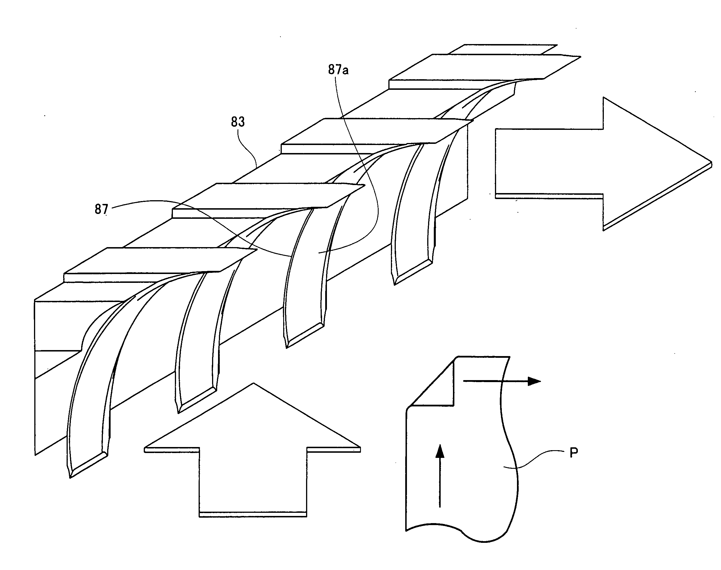
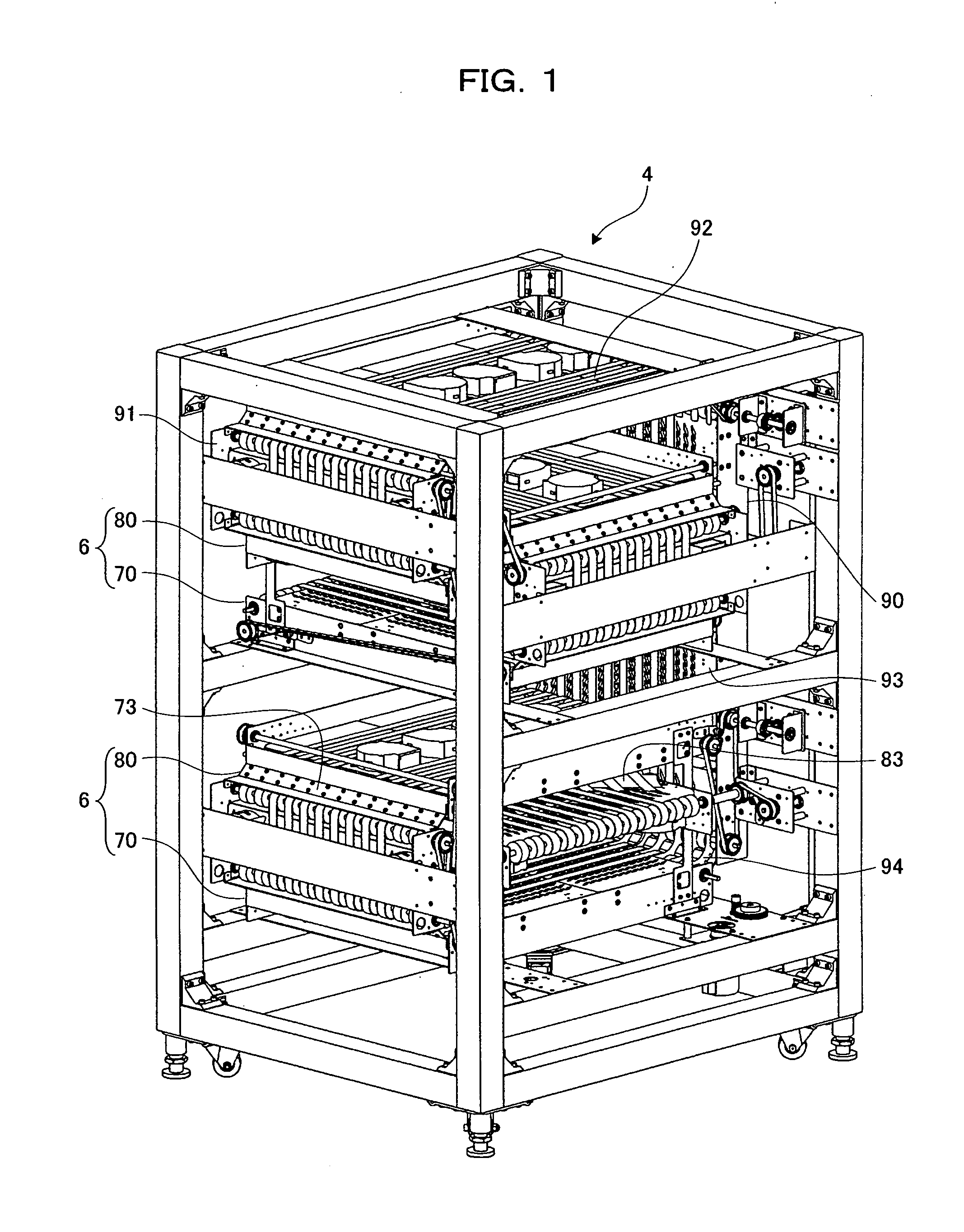
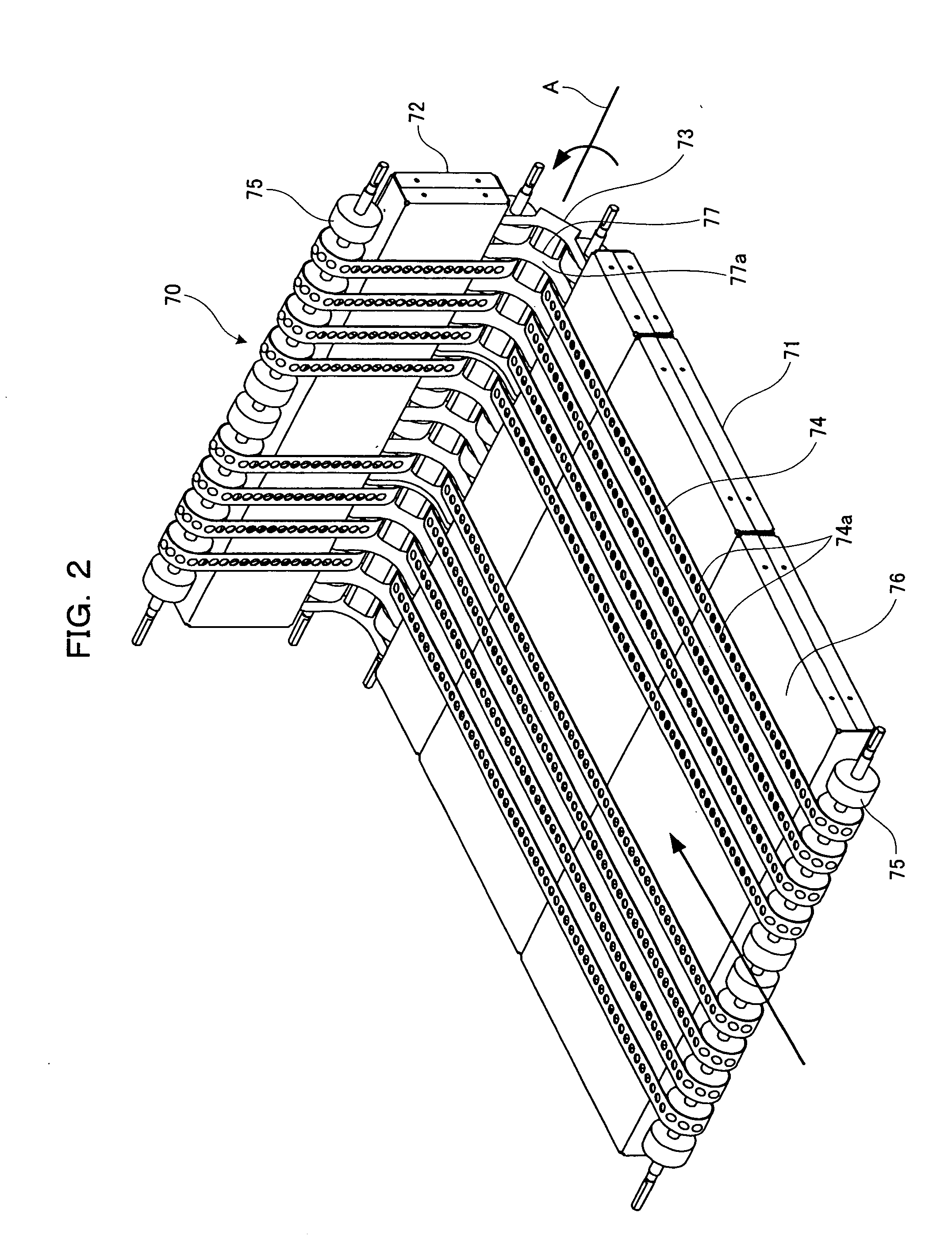
[0052]An inkjet printer 1 is made up of a paper feed mechanism 2, a printer body 3, a paper inverting mechanism 4, and a paper receiving mechanism 5. In this configuration, the printer body 3 performs printing by jetting water-based ink onto a surface of a sheet of paper according to an inkjet printing system. The paper inverting mechanism 4 is a combination of a plurality of inverting transfer units 6 which are respectively disposed on a top s...


PUM

PropertyMeasurementUnit
inversion angleaaaaaaaaaa
center distanceaaaaaaaaaa
angleaaaaaaaaaa

Abstract

Guide ribs have curved inversion/transfer surfaces from an inversion start point corresponding to a first transport surface to an inversion end point corresponding to a second transport surface.

Description

FIELD OF THE INVENTION[0001]The present invention relates to a paper transport apparatus and a technique of inverting a sheet of paper when changing a transport direction of the sheet on a transport path of the sheet in a printer and so on.BACKGROUND OF THE INVENTION[0002]Conventionally, this kind of apparatus includes a paper feeder as disclosed in, for example, Japanese Patent Laid-Open No. 10-95550. The paper feeder includes a paper feed tray for loading sheets of paper, a feeding part for feeding, one by one, the sheets of paper loaded on the paper feed tray, a turn guide for changing the transport direction of the sheet of paper fed from the paper feed tray by the feeding part, and a plurality of ribs formed on the turn guide so as to have long shapes along the transport direction of the sheets of paper. The sheets of paper loaded on the paper feed tray are fed one by one and the ribs on the turn guide change the transport directions of the sheets of paper.[0003]Further, Japane...

Claims


Application Information

Patent Timeline
Patent Type & Authority Applications(United States)
IPC IPC(8): B65H5/00
CPCB65H5/224B65H11/007B65H2511/20B65H2511/13B65H2511/12B65H2404/693B65H2301/3423B65H29/58B65H15/00B65H29/242B65H29/52B65H2220/01B65H2220/02B65H2220/11B65H15/008
Inventor SUGIYAMA, YOSHIHIDETANIMOTO, NOBUKIYAMAMOTO, KAZUYATAKAHASHI, KATSUNORI
Owner SEIKO EPSON CORP
Why Eureka
Try Eureka