Control apparatus and control method for vibration wave driven apparatus

a control apparatus and vibration wave technology, applied in electrical devices, piezoelectric/electrostrictive/magnetostrictive devices, piezoelectric/electrostriction/magnetostriction machines, etc., can solve problems such as dead zones, phase difference control and voltage control do not have a wide dynamic range, and excellent positioning accuracy

Active Publication Date: 2009-03-12
CANON KK
View PDF1 Cites 39 Cited by
  • Summary
  • Abstract
  • Description
  • Claims
  • Application Information

AI Technical Summary

Benefits of technology

[0036]According to a first aspect of this invention, there is provided a control apparatus for a vibration wave driven apparatus that applies driving signals to a vibrator including an electro-mechanical energy conversion element to thereby produce an oval motion of a driving section of the vibrator by which a driven body made in contact with the driving section is moved, comprising an operation amount determining unit adapted to determine an operation amount of the vibrator, a frequency determining unit adapted to determine a frequency of the driving signals based on the operation amount, and an oval ratio determining unit adapted to determine an oval ratio of the oval motion by changing a phase difference between the driving signals based on the operation amount, wherein the frequency determining unit sets the frequency of the driving signals to a frequency upper limit value when the phase difference between the driving signals is changed by the oval ratio determining unit, and sets the frequency of driving signals to a frequency lower than the frequency upper limit value when the phase difference between the driving signals is not changed by the oval ratio determining unit.
[0037]According to a second aspect of this invention, there is provided a control apparatus for a vibration wave driven apparatus that applies driving signals to a vibrator including an electromechanical energy conversion element to thereby produce an oval motion of a driving section of the vibrator by which a driven body made in contact with the driving section is moved, comprising an operation amount determining unit adapted to determine an operation amount of the vibrator, a frequency determining unit adapted to determine a frequency of the driving signals based on the operation amount, and an oval ratio determining unit adapted to determine an oval ratio of the oval motion by changing a voltage of the driving signals based on the operation amount, wherein the frequency determining unit sets the frequency of the driving signals to a frequency upper limit value when the voltage of the driving signals is changed by the oval ratio determining unit, and sets the frequency of the driving signals to a frequency lower than the frequency upper limit value when the voltage of the driving signals is not changed by the oval ratio determining unit.

Problems solved by technology

On the other hand, the phase difference control and the voltage control do not have a wide dynamic range but excellent in positioning accuracy.
This results in a possibility that a dead zone is caused in the control by the vibration wave driven apparatus.

Method used


Image

  • Control apparatus and control method for vibration wave driven apparatus
  • Control apparatus and control method for vibration wave driven apparatus
  • Control apparatus and control method for vibration wave driven apparatus

Examples


first embodiment

[0066]In a first embodiment of this invention, a control apparatus will be described that controls a vibration-type actuator (vibration wave driven apparatus) by a combination of frequency control and phase difference control.

[0067](Construction of the Control Apparatus of the First Embodiment)

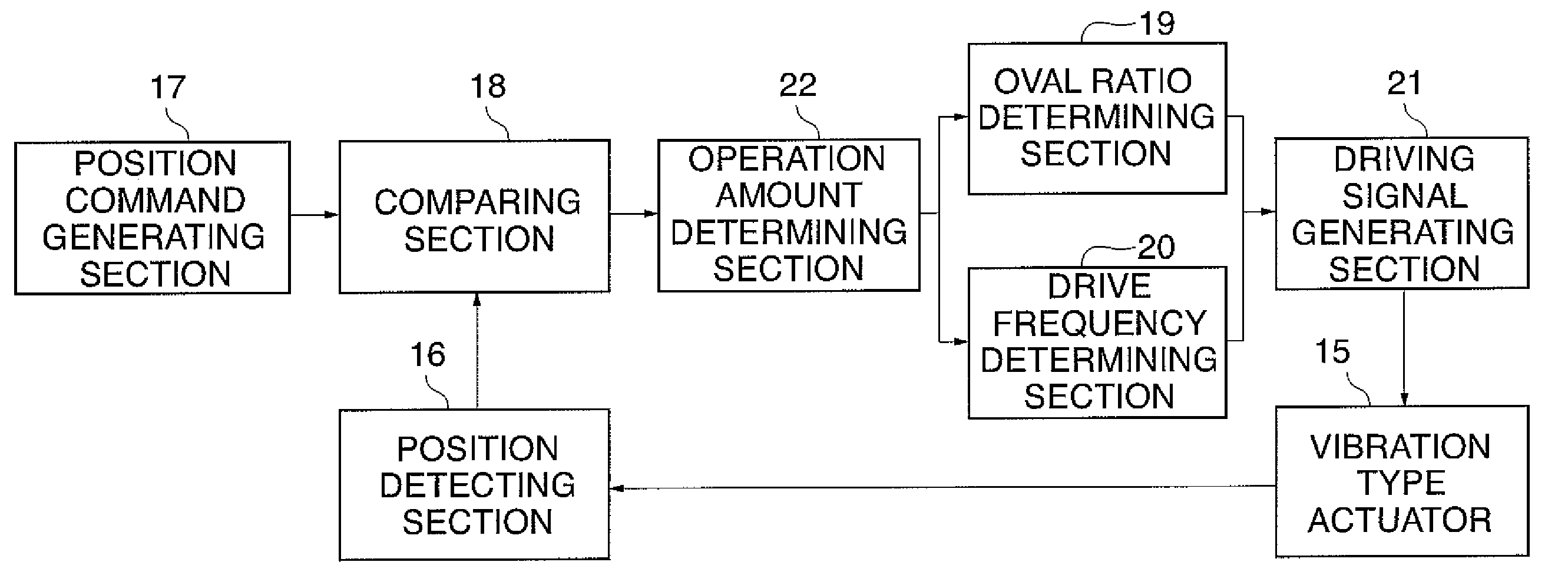
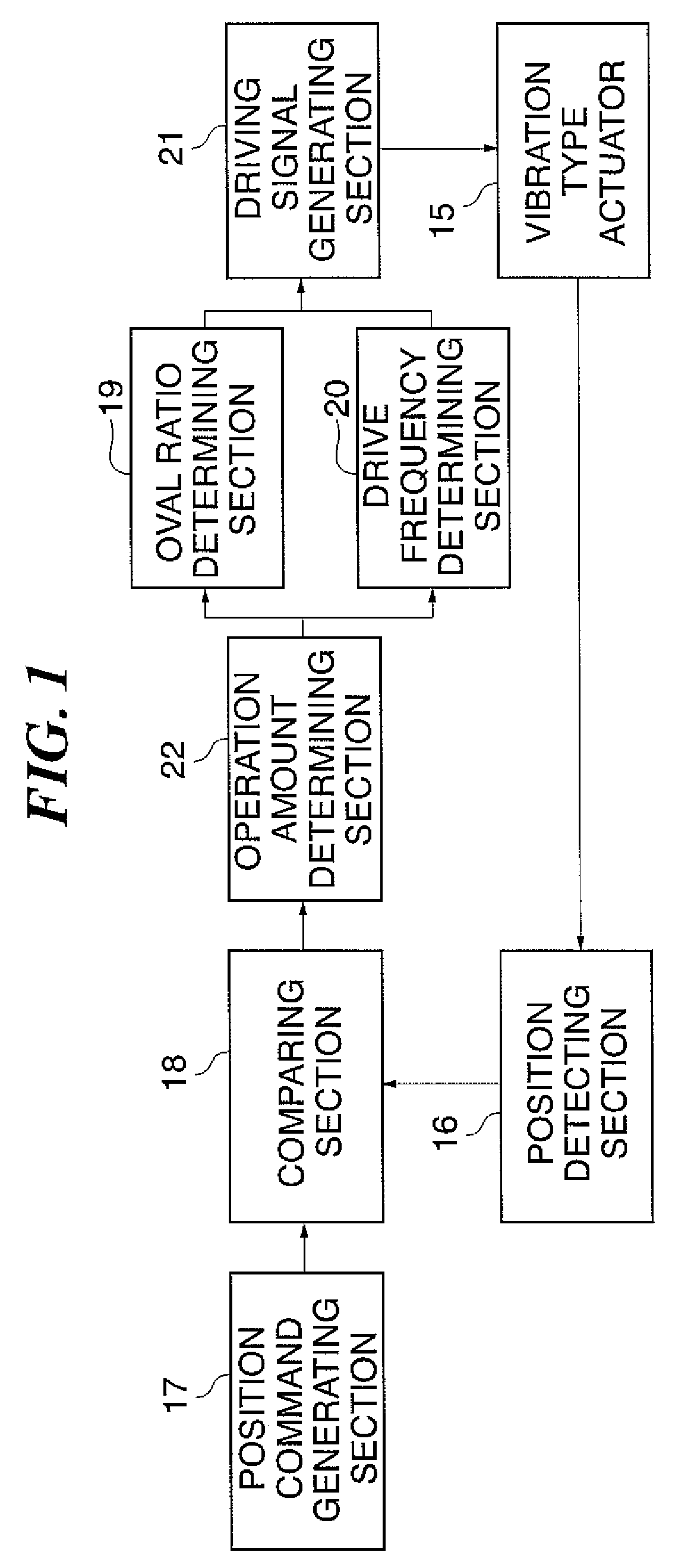
[0068]FIG. 1 shows in block diagram the construction of the control apparatus for the vibration-type actuator according to the first embodiment of this invention.

[0069]The control apparatus includes a position command generating section 17 for generating a target value of a stop position of the driven body. The position command generating section 17 is connected at its output side with an operation amount determining section 22 via a comparing section 18. The comparing section 18 compares a target value, which is output from the position command generating section 17, with a current position of the driven body, which is output from a position detecting section 16. In accordance with a result o...

second embodiment

[0102]In the first embodiment, the arrangement has been described by way of example, in which the vibration-type actuator is driven by a combination of frequency control and phase difference control. In a second embodiment, an arrangement will be described, in which the vibration-type actuator is driven by a combination of frequency control and voltage control.

[0103](Construction of the Second Embodiment)

[0104]As in the first embodiment, the construction of a control apparatus of this embodiment is such as shown in FIG. 1. The construction of a vibration-type actuator is such that the piezoelectric element 5 joined to the rear surface of the elastic body 4 in FIG. 15 is polarized as shown in FIG. 21.

[0105]In the drive control of the vibration-type actuator in this embodiment, a voltage ratio between the AC voltages V1, V2 applied to the piezoelectric element 5 is controlled so as to change the oval ratio of the oval motion of the protrusions 6.

[0106]As described previously, the firs...

third embodiment

[0131]In the first embodiment, the exemplar arrangement has been described in which the vibration-type actuator is driven by a combination of the frequency control and the phase difference control.

[0132]In the third embodiment, a description will be given of an arrangement for driving a vibration-type actuator by frequency control and phase difference control and by taking into consideration a variation caused by individual differences between vibration-type actuators and a variation in characteristic due to a change in environmental temperature.

[0133](Construction of the Control Apparatus of the Third Embodiment)

[0134]FIG. 7 shows in block diagram the construction of the control apparatus for the vibration-type actuator of the third embodiment of this invention. The control apparatus for the vibration-type actuator of this embodiment corresponds to a combination of the construction shown in FIG. 1 and a parameter setting section 23 added thereto. Except for the parameter setting se...


PUM


Abstract

A vibration wave driven apparatus capable of preventing a resonance frequency of a vibrator from being shifted to a frequency side higher than a fixed drive frequency of the vibrator during the execution of phase difference control or voltage control. Driving signals are supplied from a control apparatus to a vibration-type actuator having a piezoelectric element that functions as an electromechanical energy conversion element. To control the drive of the vibration-type actuator, either a phase difference between the driving signals or a voltage of the driving signals is changed. When either the phase difference or the driving signal voltage is changed, the frequency of the driving signals is set to a predetermined frequency higher than the frequency for use when neither the phase difference nor the driving signal voltage is changed.

Description

BACKGROUND OF THE INVENTION[0001]1. Field of the Invention[0002]The present invention relates to a control apparatus and a control method for a vibration wave driven apparatus such as a vibration-type actuator.[0003]2. Description of the Related Art[0004]Heretofore, as disclosed in Japanese Laid-open Patent Publication No. 10-210775, there have been various proposals for a vibration-type actuator that produces an oval motion of predetermined mass to thereby drive a driven body. To this end, a construction such as for example shown in FIG. 15 is known.[0005]FIG. 15 shows in external perspective view an example of the basic construction of a prior art vibration-type actuator.[0006]As shown in FIG. 15, the vibration-type actuator has a vibrator that includes an elastic body 4 made of a metal material and formed into a shape of a rectangular plate. A piezoelectric element (electro-mechanical energy conversion element) 5 is joined to a rear surface of the elastic body 4, and a plurality ...

Claims


Application Information

Patent Timeline
Patent Type & Authority Applications(United States)
IPC IPC(8): H02N2/06
CPCH02N2/026H02N2/163H02N2/142H02N2/062H02N2/0015H02N2/106
Inventor KUDO, SHINYA
Owner CANON KK
Why Eureka
Try Eureka