Flexible Nanogenerators

a nano-generator and flexible technology, applied in the direction of generator/motor, piezoelectric/electrostrictive transducer, transducer type, etc., can solve the problems of battery powered systems that require frequent recharging, large energy consumption, and heavy batteries

Active Publication Date: 2009-03-12
GEORGIA TECH RES CORP
View PDF15 Cites 81 Cited by
  • Summary
  • Abstract
  • Description
  • Claims
  • Application Information

AI Technical Summary

Benefits of technology

[0009]The disadvantages of the prior art are overcome by the present invention which, in one aspect, is a small scale electrical generator that includes an elongated substrate and a first piezoelectric fine wire. The first piezoelectric fine wire is disposed along a surface of the substrate. The first piezoelectric fine wire has a first end and a spaced-apart second end. A first conductive contact secures the first end of the fine wire to a first portion of the substrate and a second conductive contact secures the second end of the fine wire to a second portion of the substrate.

Problems solved by technology

While batteries may provide the power in many such applications, batteries can be heavy and inconvenient.
Also, some battery powered systems require frequent recharging.
While the relative displacement of the threads is often on a microscopic scale, such movement involves a considerable amount of energy.
Unfortunately, there is currently no practical method of harvesting such energy.

Method used


Image

  • Flexible Nanogenerators
  • Flexible Nanogenerators
  • Flexible Nanogenerators

Examples


Embodiment Construction

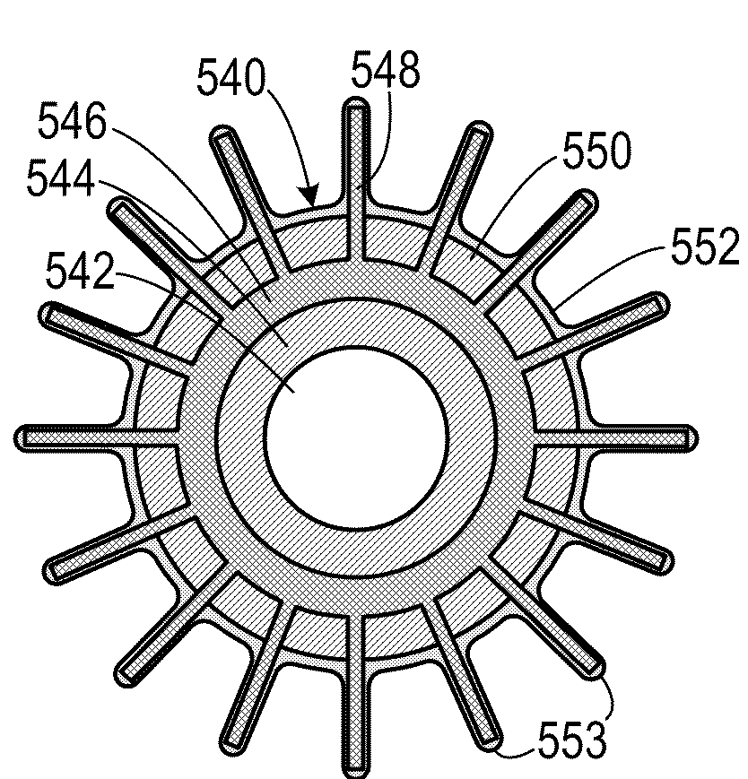
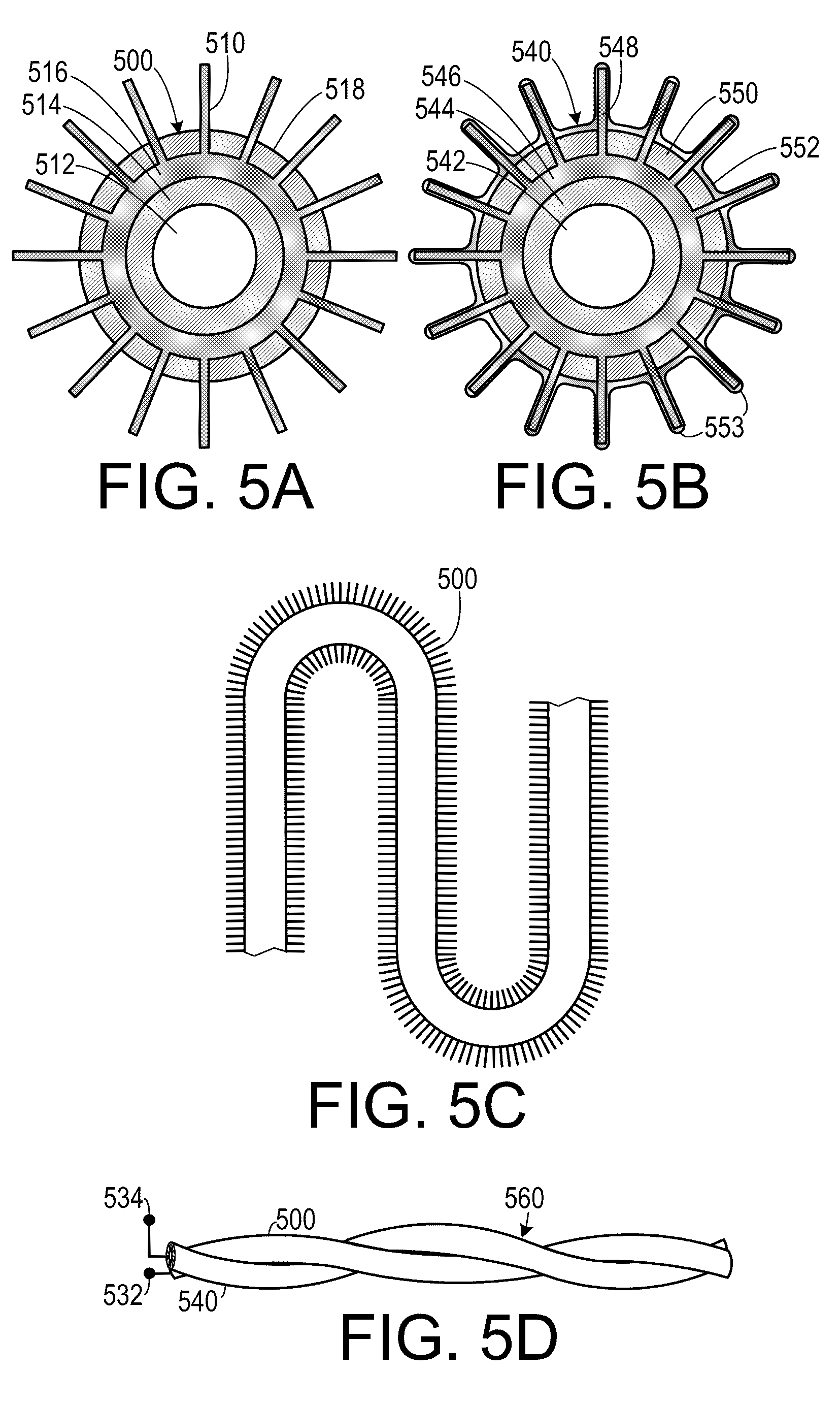
[0027]A preferred embodiment of the invention is now described in detail. Referring to the drawings, like numbers indicate like parts throughout the views. As used in the description herein and throughout the claims, the following terms take the meanings explicitly associated herein, unless the context clearly dictates otherwise: the meaning of “a,”“an,” and “the” includes plural reference, the meaning of “in” includes “in” and “on.” Also, as used herein, the term “piezoelectric fine wire” includes nano-scale piezoelectric wires and micro-scale piezoelectric wires. The term “wire” includes ribbons, rods and other elongated structures.

[0028]Relevant to the disclosure that follows, the growth of ZnO nanorods is disclosed in more detail in U.S. patent application Ser. No. 11 / 608,865, filed on Dec. 11, 2006 by Wang et al. and U.S. Pat. Nos. 7,220,310, issued on May 22, 2007 to Wang et al. and 7,351,607, issued on Apr. 1, 2008 to Wang et al., the entirety of each of which is hereby incor...


PUM

PropertyMeasurementUnit
transient voltageaaaaaaaaaa
thicknessaaaaaaaaaa
lengthaaaaaaaaaa

Abstract

A small scale electrical generator includes an elongated substrate and a first piezoelectric fine wire. The first piezoelectric fine wire is disposed along a surface of the substrate. The first piezoelectric fine wire has a first end and a spaced-apart second end. A first conductive contact secures the first end of the fine wire to a first portion of the substrate and a second conductive contact secures the second end of the fine wire to a second portion of the substrate. A fabric made of interwoven strands that includes fibers from which piezoelectric nanowires extend radially therefrom and conductive nanostructures extend therefrom is configured to generate electricity.

Description

CROSS-REFERENCE TO RELATED APPLICATION(S)[0001]This application claims the benefit of U.S. Provisional Patent Application Ser. Nos. 60,971,616, filed Sep. 12, 2007, and 61,033,642, filed Mar. 4, 2008, the entirety of each of which is hereby incorporated herein by reference.BACKGROUND OF THE INVENTION[0002]1. Field of the Invention[0003]The present invention relates to electrical power generators and, more specifically, to flexible substrate-based nano-generators.[0004]2. Description of the Prior Art[0005]Many systems require locally stored or generated electrical power to power local devices used in a variety of applications. For example, many military systems require electrical power for small scale communication and sensor systems. As another example, many medical systems employ mobile monitors and stimulators to detect and treat medical conditions of patients as they live their normal lives.[0006]While batteries may provide the power in many such applications, batteries can be he...

Claims


Application Information

Patent Timeline
Patent Type & Authority Applications(United States)
IPC IPC(8): H02N2/18H01L41/22
CPCH02N2/18Y10T29/42H01L41/317H10N30/30H10N30/07H10N30/077
Inventor WANG, ZHONG L.WANG, XUDONGQIN, YONGYANG, RUSEN
Owner GEORGIA TECH RES CORP
Why Eureka
Try Eureka