Ink jet print head

a printing head and jet technology, applied in the direction of printing and inking apparatus, can solve the problem of quick severed, and achieve the effect of high-speed and high-image-quality printing

Inactive Publication Date: 2009-03-12
CANON KK
View PDF7 Cites 9 Cited by
  • Summary
  • Abstract
  • Description
  • Claims
  • Application Information

AI Technical Summary

Benefits of technology

[0014]An object of the present invention is to provide a reliable ink jet print head and a reliable ink jet printing apparatus which enable small ink droplets to be ejected at a high frequency while preventing possible satellites and mist and which also enable high-speed and high-image-quality printing.

Problems solved by technology

As a result, an inner surface of the ejection port portion interferes with the trailing portion, which is thus quickly severed.

Method used


Image

  • Ink jet print head
  • Ink jet print head
  • Ink jet print head

Examples


first embodiment

[0029]A first embodiment of the present invention will be described with reference to FIGS. 1A, 1B, 2, and 4.

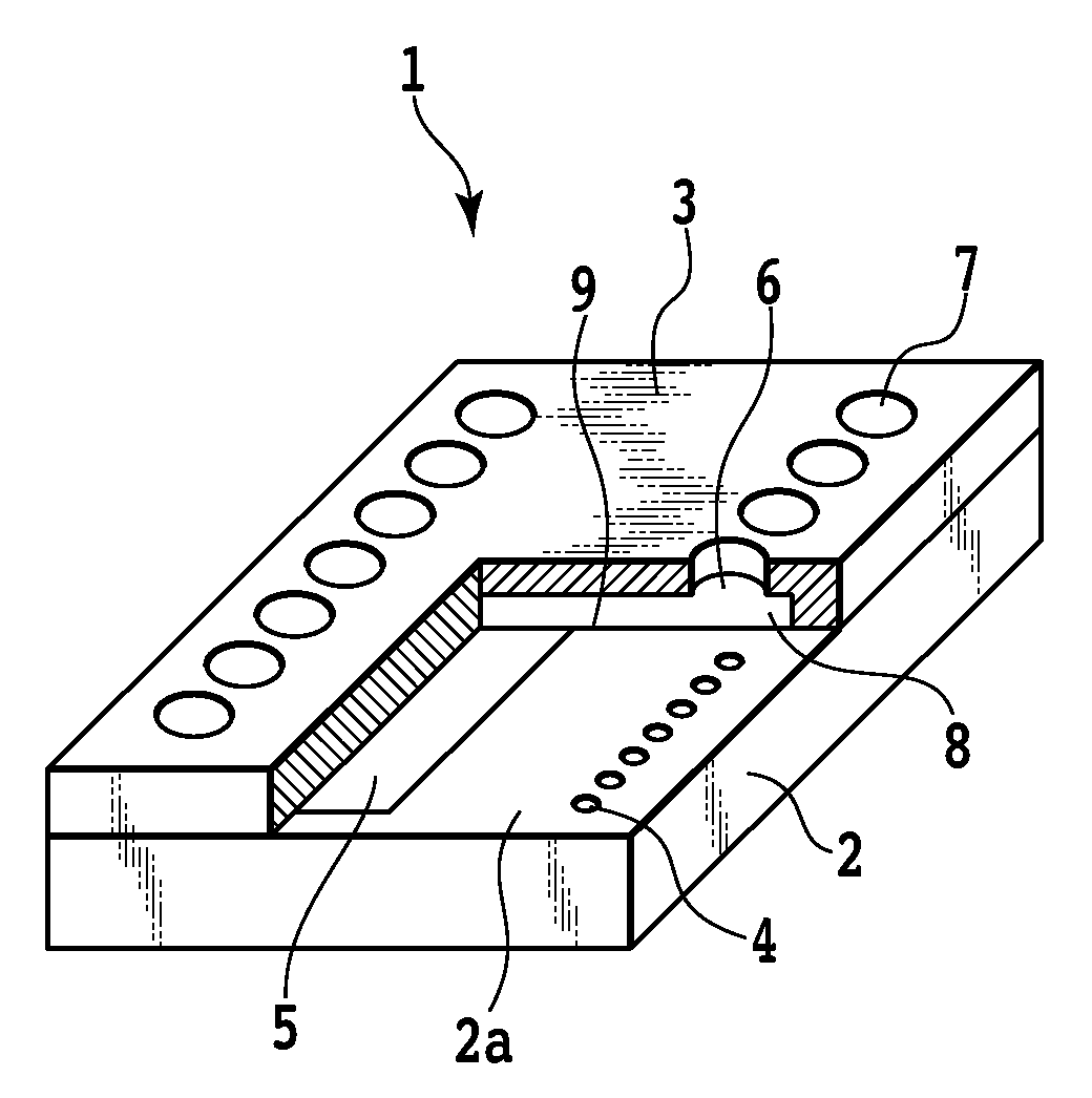
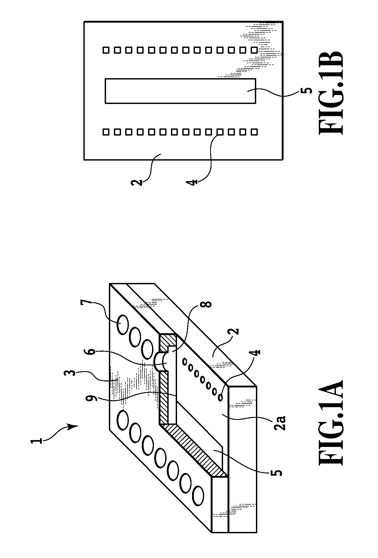
[0030]FIG. 1A is a perspective view schematically showing a partly cutaway ink jet print head 1 according to the first embodiment. The ink jet print head 1 comprises an element substrate 2 on which an electrothermal conversion element 4 serving as heat energy generating means is provided, and a channel constituting substrate (orifice plate) 3 laminated on a major surface 2a of the element substrate 2.

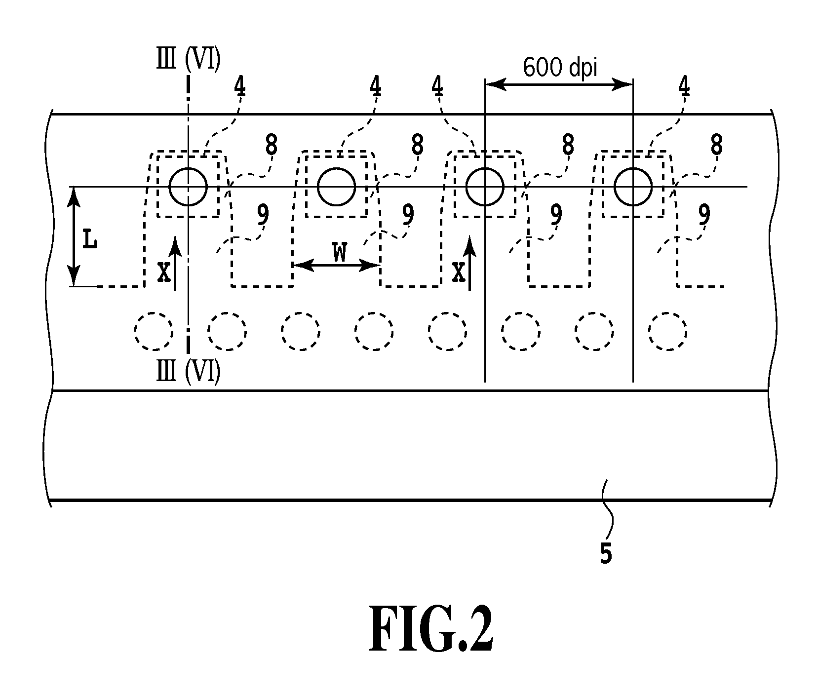
[0031]As shown in FIG. 1B, two electrothermal conversion element rows each made up of a plurality of the electrothermal conversion elements 4 are arranged the element substrate 2 in parallel across an ink supply port 5.

[0032]On the other hand, the channel constituting substrate 3 is formed of a plurality of ejection port portions 6, a plurality of bubbling chambers 8 communicating with the respective ejection port portions 6, and a plurality of ink supply channels 9 communicating...

second embodiment

[0044]A second embodiment of the present invention will be described with reference to FIGS. 6 and 7.

[0045]The ink jet print head 10 according to the second embodiment has the same basic structure as that of the ink jet print head 10 according to the first embodiment. The ink jet print head 10 according to the second embodiment has the structure shown in FIGS. 1A, 1B, and 2. Thus, the same components in FIGS. 6 and 7 as those shown in FIGS. 1A, 1B, and 2 or components in FIGS. 6 and 7 corresponding to those shown in FIGS. 1A, 1B, and 2 are denoted by the same reference numerals. FIG. 6 is a vertically sectional side view of the nozzle in FIG. 1, the view being taken along line VI-VI in FIG. 1. FIG. 7 is a bottom view of the ejection port portion shown in FIG. 6 as viewed from the side of the ink supply channel.

[0046]In the ink jet print head 10 according to the second embodiment, the shape of the ejection port portion 16, formed in the channel constituting member 3, is different fro...


PUM


Abstract

An object of the present invention is to provide a reliable ink jet print head that enables small ink droplets to be ejected at a high frequency while preventing possible satellites and mist. In the present invention, a bubbling chamber in which an energy generating element is disposed communicates, via an ejection port portion, with an ejection port 7 provided opposite the energy generating element. The ejection port portion is formed such that flow resistance to ink is lower in an area of the ejection port portion which is positioned inward from a center of the ejection port in an ink supply direction of ink flowing along the ink supply channel, than in an area of the ejection port portion which is positioned outward from the center of the ejection port.

Description

BACKGROUND OF THE INVENTION[0001]1. Field of the Invention[0002]The present invention relates to an ink jet print head that ejects ink droplets to print media, and in particular, to an ink jet print head suitable for high-speed and high-definition printing.[0003]2. Description of the Related Art[0004]With the increased operation speed and improved image quality of ink jet printing apparatuses, attempts have been made to reduce the size of droplets ejected from a print head and to increase ejection frequency.[0005]The opening area of each ejection port in the print head needs to be reduced in order to reduce the size of ejected droplets. However, the reduced opening area of the ejection port increases the flow resistance of a liquid in a portion (ejection port portion) that communicates with the ejection port. This may prevent desired ejection performance and efficiency from being obtained. Thus, ink jet print heads are disclosed in Japanese Patent Laid-Open Nos. 2004-042651 and 2004...

Claims


Application Information

Patent Timeline
Patent Type & Authority Applications(United States)
IPC IPC(8): B41J2/14B41J2/04
CPCB41J2/1404B41J2202/11B41J2002/14387B41J2002/14185B41J2002/14169
Inventor MATSUMOTO, MITSUHIRO
Owner CANON KK
Why Eureka
Try Eureka