
Photosensitive resin composition, method of forming level difference pattern using the photosensitive resin composition, and method of producing ink jet head

a resin composition and resin technology, applied in the direction of photomechanical treatment, photosensitive materials, instruments, etc., can solve the problems of high difficulty in processing a thin ink flow path structure plate with high accuracy, inconvenience, dissolution and deformation, etc., to achieve high sensitivity, reduce processing time, and high speed and high image quality printing

Inactive Publication Date: 2010-03-02
CANON KK
View PDF25 Cites 7 Cited by
  • Summary
  • Abstract
  • Description
  • Claims
  • Application Information

AI Technical Summary

Benefits of technology

[0020]The present invention has been made for solving each of the problems described above, and an object of the present invention is to expand a range of selection of photosensitive wavelength while increasing the exposure sensitivity of a positive type photosensitive resin composition using an acrylic resin having a carboxylic anhydride structure. Another object of the present invention is to provide: a method of forming a pattern with which an ink flow path the shape of which changes in a height direction from a substrate to a discharge port can be formed with high accuracy and high efficiency by means of a positive type photosensitive resin composition; and a method of producing an ink jet head using the same.
[0028]The positive type photosensitive resin composition of the present invention has high sensitivity and can reduce a processing time in a pattern formation process. Furthermore, according to the present invention, a high-accuracy ink jet head which enables high-speed-and-high-image-quality printing can be produced by means of a simple method with high efficiency and in high yield. In addition, according to the present invention, a level difference pattern useful in producing such an ink jet head can be formed with high accuracy and high efficiency.

Problems solved by technology

However, it is extremely difficult to process a thin ink flow path structure plate with high accuracy before the plate is attached to a substrate.
As a result, a decomposition reaction or the like of the positive type resist material is promoted, with the result that inconvenience may occur.
Furthermore, the negative type resist is applied onto the ink flow path pattern formed by means of the positive type resist, so there may arise problems such as the dissolution and deformation of the ink flow path pattern upon application of the negative type resist.
However, excimer laser used for such processing, which is different from excimer laser used for exposure of a semiconductor, is laser having high brightness in a wide bandwidth.
Therefore, it is very difficult to stabilize laser illuminance while suppressing a fluctuation in illuminance in a plane to be irradiated with laser.
Furthermore, in many cases, a minute pattern cannot be formed owing to a taper attached to a plane to be processed with laser /
Only one exposing device can separate an irradiation wavelength by means of an optical filter, in which case an expensive optical filter is needed.
Furthermore, when a mold constituting a part serving as an ink flow path has a two-layer structure, an applying step must be performed at least twice and a prebaking step must be performed at least twice, resulting in an increase in number of steps.

Method used


Image

  • Photosensitive resin composition, method of forming level difference pattern using the photosensitive resin composition, and method of producing ink jet head
  • Photosensitive resin composition, method of forming level difference pattern using the photosensitive resin composition, and method of producing ink jet head
  • Photosensitive resin composition, method of forming level difference pattern using the photosensitive resin composition, and method of producing ink jet head

Examples


embodiment 1

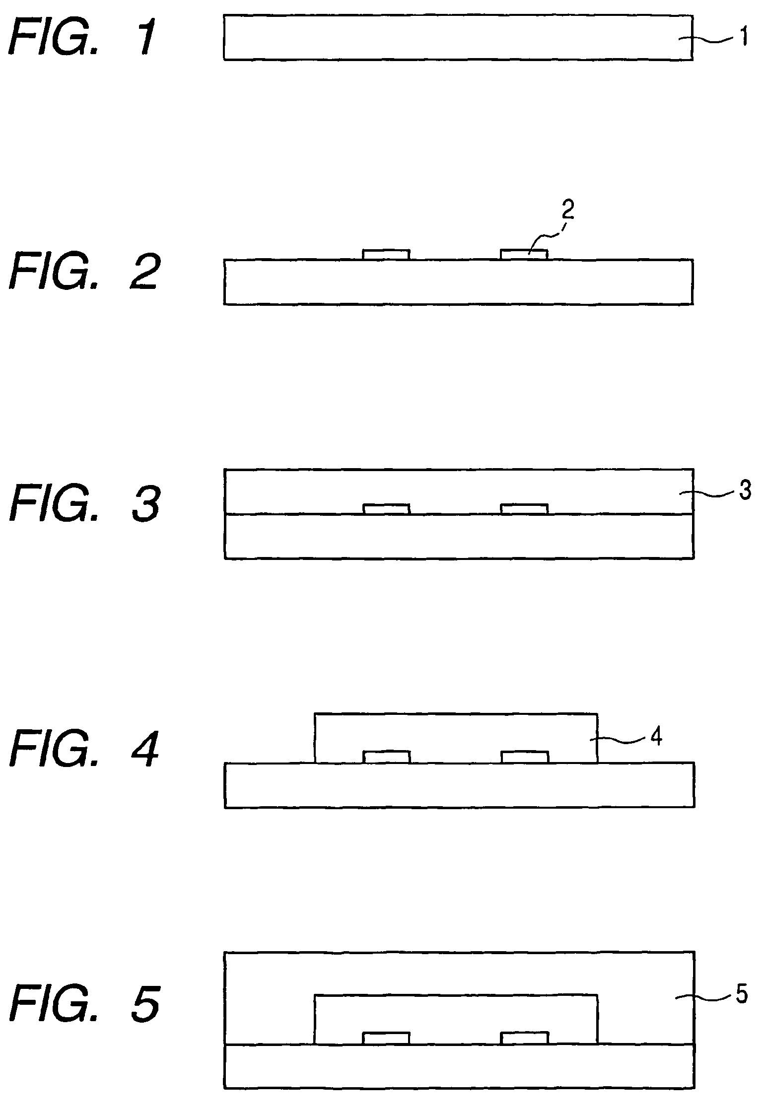
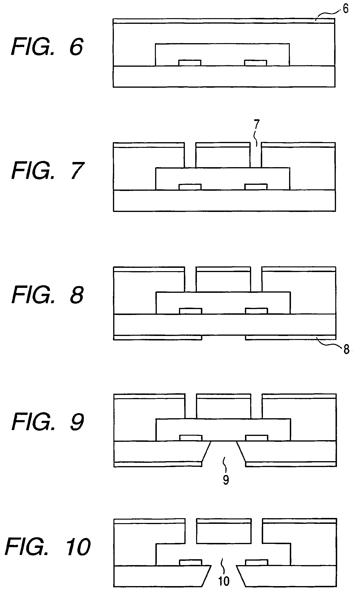
[0073]FIGS. 1 to 10 each schematically show the cross section of the structure of an ink jet head and a method of producing the same. First, a substrate 1 as shown in FIG. 1 is prepared. The shape, material, and the like of the substrate are not particularly limited as long as the substrate can function as part of an ink flow path constitution member, and can also function as a support for a material layer with which an ink flow path and an ink discharge port to be described later are formed. In this example, a silicon substrate is used because an ink supply port penetrating through the substrate is formed by means of anisotropic etching to be described later.

[0074]A desired number of ink discharge pressure generating elements 2 such as an electrothermal converting element and a piezoelectric element are arranged on the substrate 1 (FIG. 2). The ink discharge pressure generating elements 2 provide an ink liquid with discharge energy for discharging ink liquid droplets, whereby recor...

embodiment 2

[0089]FIGS. 11 to 22 each schematically show the cross section of the structure of an ink jet head and a method of producing the same. First, a substrate 1 as shown in FIG. 11 is prepared. The shape, material, and the like of the substrate are not particularly limited as long as the substrate can function as part of an ink flow path constitution member, and can also function as a support for a material layer with which an ink flow path and an ink discharge port to be described later are formed. In this example, a silicon substrate is used because an ink supply port penetrating through the substrate is formed by means of anisotropic etching to be described later.

[0090]A desired number of ink discharge pressure generating elements 2 such as an electrothermal converting element and a piezoelectric element are arranged on the substrate 1 (FIG. 12). The ink discharge pressure generating elements 2 provide ink with discharge energy for discharging the ink, whereby recording is performed. ...

embodiment 3

[0105]FIGS. 23 to 33 each schematically show the cross section of the structure of an ink jet head and a method of producing the same. In addition, FIGS. 34 and 35 each show the sensitivity property of a positive type resist to be used in the present invention.

[0106]First, a substrate 1 as shown in FIG. 23 is prepared. The shape, material, and the like of the substrate are not particularly limited as long as the substrate can function as part of a liquid flow path constitution member, and can also function as a support for a material layer with which an ink flow path and an ink discharge port to be described later are formed. In this example, a silicon substrate is used because an ink supply port penetrating through the substrate is formed by means of anisotropic etching to be described later.

[0107]A desired number of ink discharge pressure generating elements 2 such as an electrothermal converting element and a piezoelectric element are arranged on the substrate 1 (FIG. 24). The in...


PUM

PropertyMeasurementUnit
mass %aaaaaaaaaa
temperatureaaaaaaaaaa

Abstract

To provide a positive type photosensitive resin composition, containing at least an acrylic resin having a carboxylic anhydride structure in a molecule, and a compound that generates an acid when irradiated with light.

Description

TECHNICAL FIELD[0001]The present invention relates to a photosensitive resin composition that can be suitably used in producing an ink jet head for generating a recording liquid droplet for use in an ink jet recording method. The present invention also relates to: a method of forming a level difference pattern and a method of producing an ink jet head each using the photosensitive resin composition; and an ink jet head produced by the method of producing an ink jet head.BACKGROUND ART[0002]An ink jet head applicable to an ink jet recording method (liquid discharge recording method) involving discharging a recording solution such as ink to carry out recording is generally equipped with: an ink flow path; a liquid discharge energy generating portion placed in part of the ink flow path; and a fine ink discharge port (called an “orifice”) for discharging ink in the ink flow path by means of energy from the liquid discharge energy generating portion. Examples of a method of producing suc...

Claims


Application Information

Patent Timeline
Patent Type & Authority Patents(United States)
IPC IPC(8): G03F7/40B41J2/135B41J2/16G03F7/039
CPCB41J2/1603B41J2/1631G03F7/2024G03F7/0392B41J2/1639G03F7/322
Inventor SHIBA, SHOJIISHIKURA, HIROEOKANO, AKIHIKO
Owner CANON KK
Learn More