Display device

a display device and display screen technology, applied in non-linear optics, instruments, optics, etc., can solve the problems of adhesive protruding and sagging from the substrate, yellowish, deformation severe, etc., to prevent cracking, sufficiently harden, and prevent sagging

Active Publication Date: 2009-03-12
PANASONIC LIQUID CRYSTAL DISPLAY CO LTD +1
View PDF15 Cites 36 Cited by
  • Summary
  • Abstract
  • Description
  • Claims
  • Application Information

AI Technical Summary

Benefits of technology

[0081]According to the present invention, the entirety of the sides of a polarizing plate is covered with the adhesive for pasting the transparent cover to the display panel, and therefore, inconsistency in the display resulting from expansion of the polarizing plate in the vicinity of an end portion caused by moisture can be prevented. Furthermore, the form of the outer periphery of the adhesive for pasting the transparent cover to the display panel in a plane is uneven, and thus, the adhesive can be prevented from sagging when the display panel and the transparent cover are pasted together.
[0082]In addition, according to the present invention, an adhesive intervenes between the transparent cover and the drive circuit in the case where the drive circuit mounted on the display panel is coated with a transparent cover, and thus, the transparent cover can be prevented from cracking when pressed.
[0083]In addition, according to the present invention, an opening is created in the light blocking film of the transparent cover in the case where an adhesive which can be hardened through irradiation with light is used as the adhesive for pasting the transparent cover to the display panel, and therefore, the adhesive can be sufficiently hardened.
[0084]Other effects of the present invention will become clearer from the description throughout the entire specification.

Problems solved by technology

As a result, as shown in FIG. 12, moisture enters from the side of the polarizing plate POL2, and a problem arises, such that the polarizing plate POL2 expands in the vicinity of the end portion.
This deformation becomes severe as the adhesive ADH becomes thinner.
When this inconsistent gap region IRG reaches the inside of the display region AR, a problem arises, such that yellowish, frame-like inconsistency, for example, appears in the display.
In the case of the configuration shown in Patent Documents 1 and 2, when the transparent cover and the liquid crystal display panel shift in position at the time of pasting, a problem arises, such that the adhesive protrudes and sags from the substrate on the upper side (corresponding to the second substrate SUB2 in FIG. 11).

Method used


Image

  • Display device
  • Display device
  • Display device

Examples


first embodiment

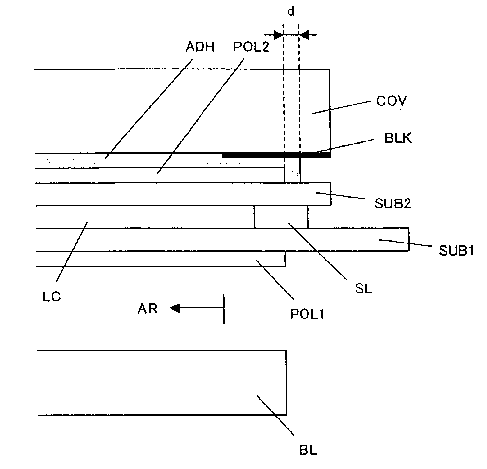
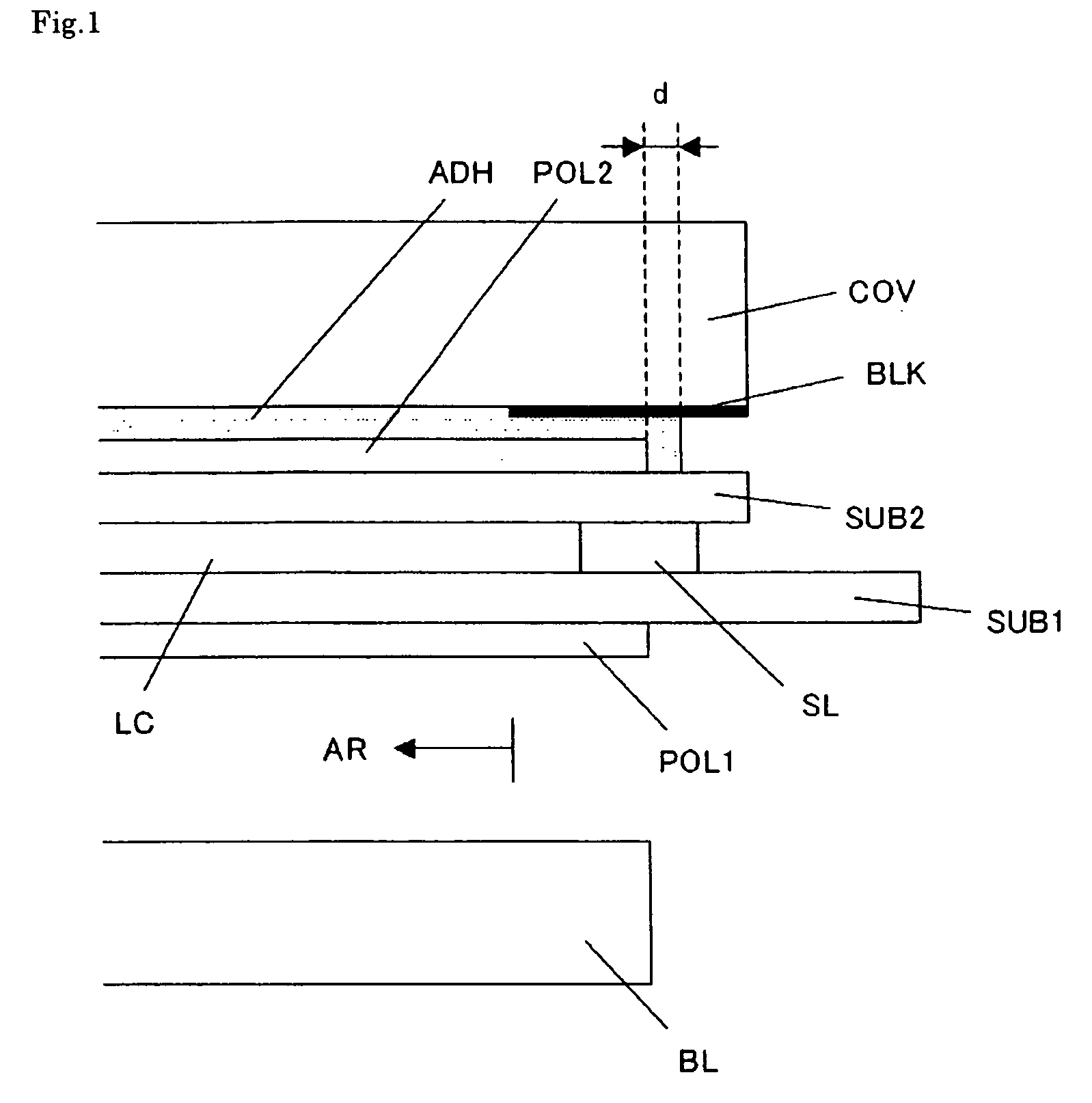
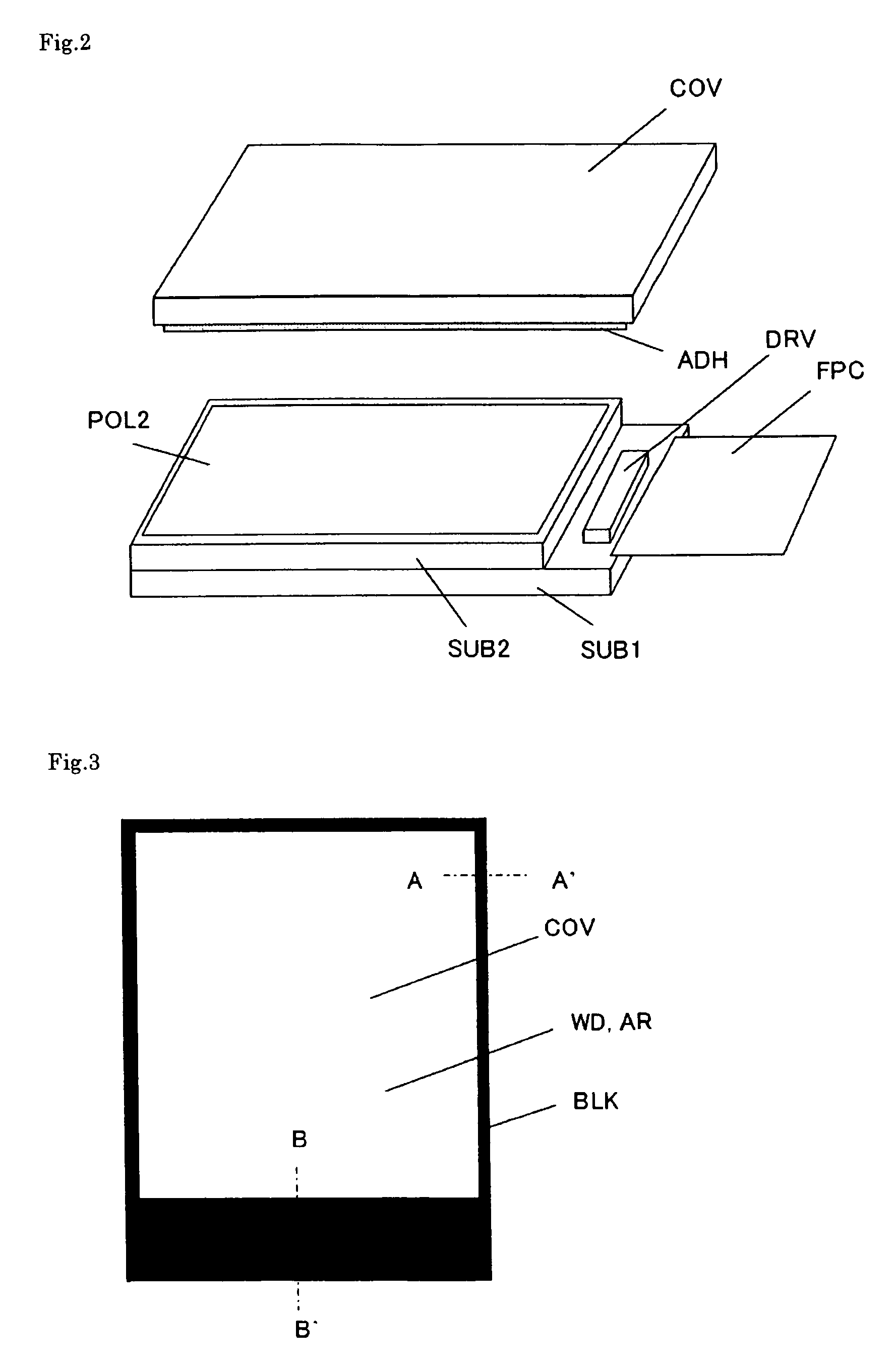
[0114]FIG. 1 is a cross sectional diagram showing the display device according to the first embodiment of the present invention. FIG. 2 is a perspective diagram showing the manner in which the display panel and the transparent cover are pasted together according to an example of the present invention. FIG. 3 is a plan diagram showing the transparent cover according to one example of the present invention.

[0115]Here, a case where a liquid crystal display panel is used as the display panel is described as an example. As shown in FIG. 1, the liquid crystal display panel has an insulating, transparent first substrate SUB1 and second substrate SUB2 formed of glass, for example. In addition, the first substrate SUB1 and the second substrate SUB2 are pasted together using a sealing material SL. A liquid crystal layer LC is sandwiched between the first substrate SUB1 and the second substrate SUB2. A sealing material SL is formed in the peripheral portion outside the display region AR of the...

second embodiment

[0127]FIG. 7 is a cross sectional diagram showing the display device according to the second embodiment of the present invention. FIG. 7 is a cross sectional diagram showing a portion corresponding to FIG. 1. The basic configuration in the second embodiment is the same as in the first embodiment. The difference from the first embodiment is the location of the end portion of the polarizing plate POL2.

[0128]A case where the end portion of the polarizing plate POL2 is in such a location as to overlap with the sealing material SL is shown as an example of the above described embodiment in FIG. 1. However, there is a problem with this case, such that the adhesive ADH cannot protrude by much of a distance d. Thus, in the second embodiment, which is the present embodiment, an end portion of the polarizing plate POL2 is located on the side closer to the display region AR than the sealing material SL provided around the display region AR.

[0129]As a result, it becomes easy to secure a large d...

third embodiment

[0131]FIG. 8 is a cross sectional diagram showing the display device according to the third embodiment of the present invention. FIG. 8 is a cross sectional diagram along line B-B′ in FIG. 3. The basic configuration in the third embodiment is the same as in the first and second embodiments, and therefore, mainly portions which are different in the configuration are described.

[0132]In the present embodiment, a drive circuit DRV is mounted in the region of the first substrate SUB1 which protrudes from the second substrate SUB2, as described in the first embodiment. In addition, the transparent cover COV is provided so as to cover the drive circuit DRV. In the case where the transparent cover COV is provided so as to cover the drive circuit DRV and there is a space between the two, however, there is a possibility that a problem may arise, such that the transparent cover COV cracks when pressed.

[0133]Therefore, in the present embodiment, the adhesive ADH is also provided between the tra...


PUM

PropertyMeasurementUnit
thicknessaaaaaaaaaa
thicknessaaaaaaaaaa
thicknessaaaaaaaaaa

Abstract

The present invention is directed to providing a technology for display devices where a transparent cover is pasted on a display panel according to which inconsistencies resulting from expansion of the polarizing plate in the vicinity of an end portion caused by moisture can be prevented, and the adhesive can be prevented from sagging when the display panel and the transparent cover are pasted together. A display device according to the invention is provided with: a liquid crystal display panel having a first substrate, a second substrate provided on the viewer side of the above described first substrate and a liquid crystal layer sandwiched between the above described first substrate and the above described second substrate; and a transparent cover pasted on the surface of the above described liquid crystal display panel on the above described viewer side using an adhesive. The above described liquid crystal display panel has a polarizing plate between the above described second substrate and the above described transparent cover. The above described adhesive covers the entirety of a side of the above described polarizing plate, and the form of the outer periphery of the above described adhesive in a plane is uneven.

Description

[0001]The present application claims priority from Japanese application JP2007-236102 filed on Sep. 12, 2007, the content of which is hereby incorporated by reference into this application.BACKGROUND OF THE INVENTION[0002](1) Field of the Invention[0003]The present invention relates to a display device where a transparent cover is pasted on the surface of a display panel using an adhesive.[0004](2) Related Art Statement[0005]Liquid crystal display devices having a liquid crystal display panel, for example, are known as display devices. In many cases, a transparent cover, such as of an acryl resin, is provided on such a liquid crystal display panel on the viewer side (front side). This transparent cover works as a protective cover plate. However, the transparent cover is provided at a predetermined distance from the liquid crystal display panel, and therefore, there is an air layer between the transparent cover and the liquid crystal display panel. Therefore, there is unnecessary int...

Claims


Application Information

Patent Timeline
Patent Type & Authority Applications(United States)
IPC IPC(8): G02F1/1335
CPCG02F1/133308G02F1/13452G02F2202/28G02F2001/133562G02F2201/50G02F2001/133311G02F1/133311G02F1/133562
Inventor ISHII, KATSUHIKOTAKAHASHI, RISASANO, YASUSHI
Owner PANASONIC LIQUID CRYSTAL DISPLAY CO LTD
Why Eureka
Try Eureka