
Providing feedback in a MIMO system

a technology of mimo and feedback, applied in the field of communication systems, can solve the problems of no fast algorithms, high computational burden, and high complexity of brute force implementation of step 2 of the above algorithm

Active Publication Date: 2009-03-12
ALCATEL LUCENT SAS
View PDF16 Cites 10 Cited by
  • Summary
  • Abstract
  • Description
  • Claims
  • Application Information

AI Technical Summary

Benefits of technology

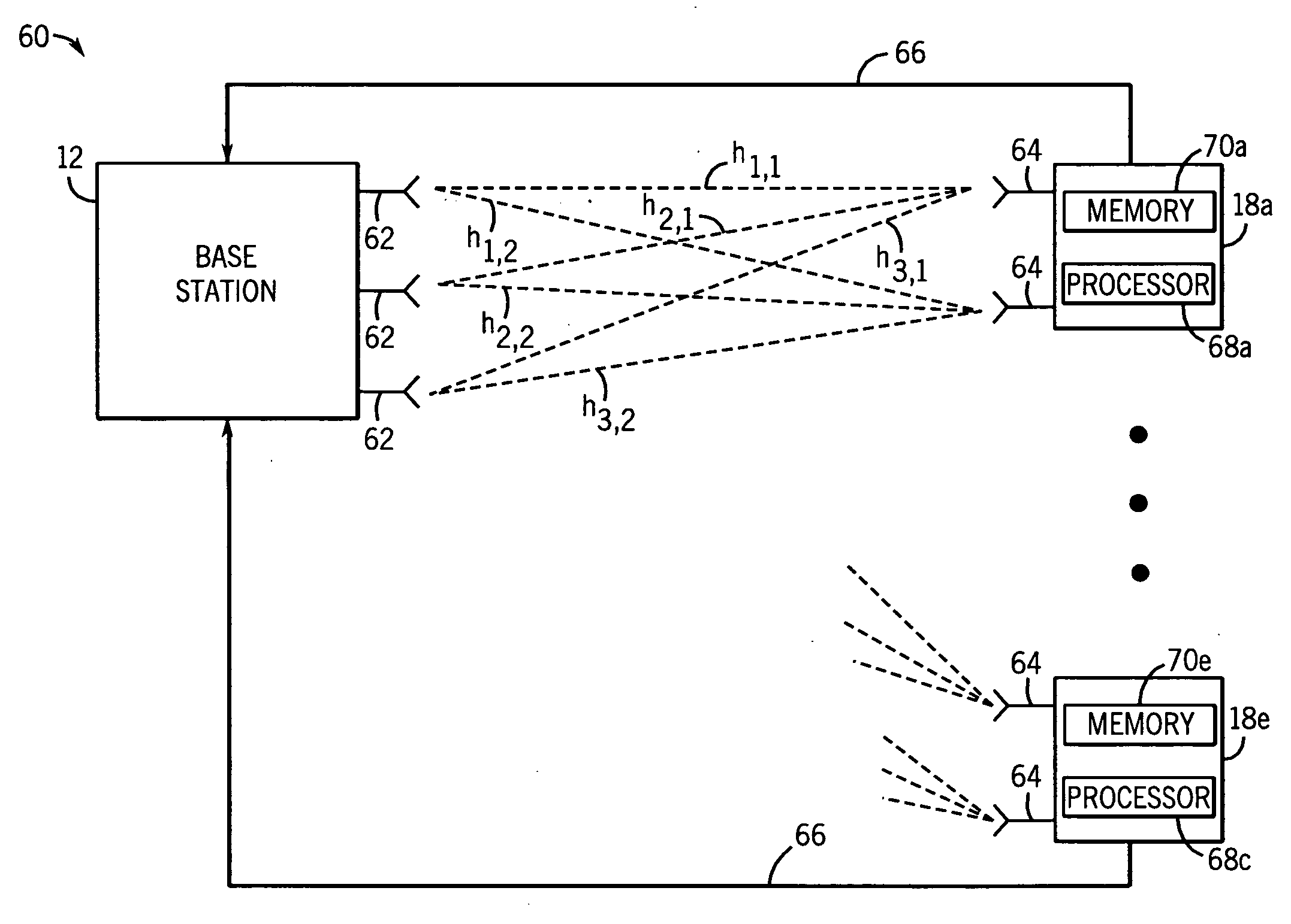
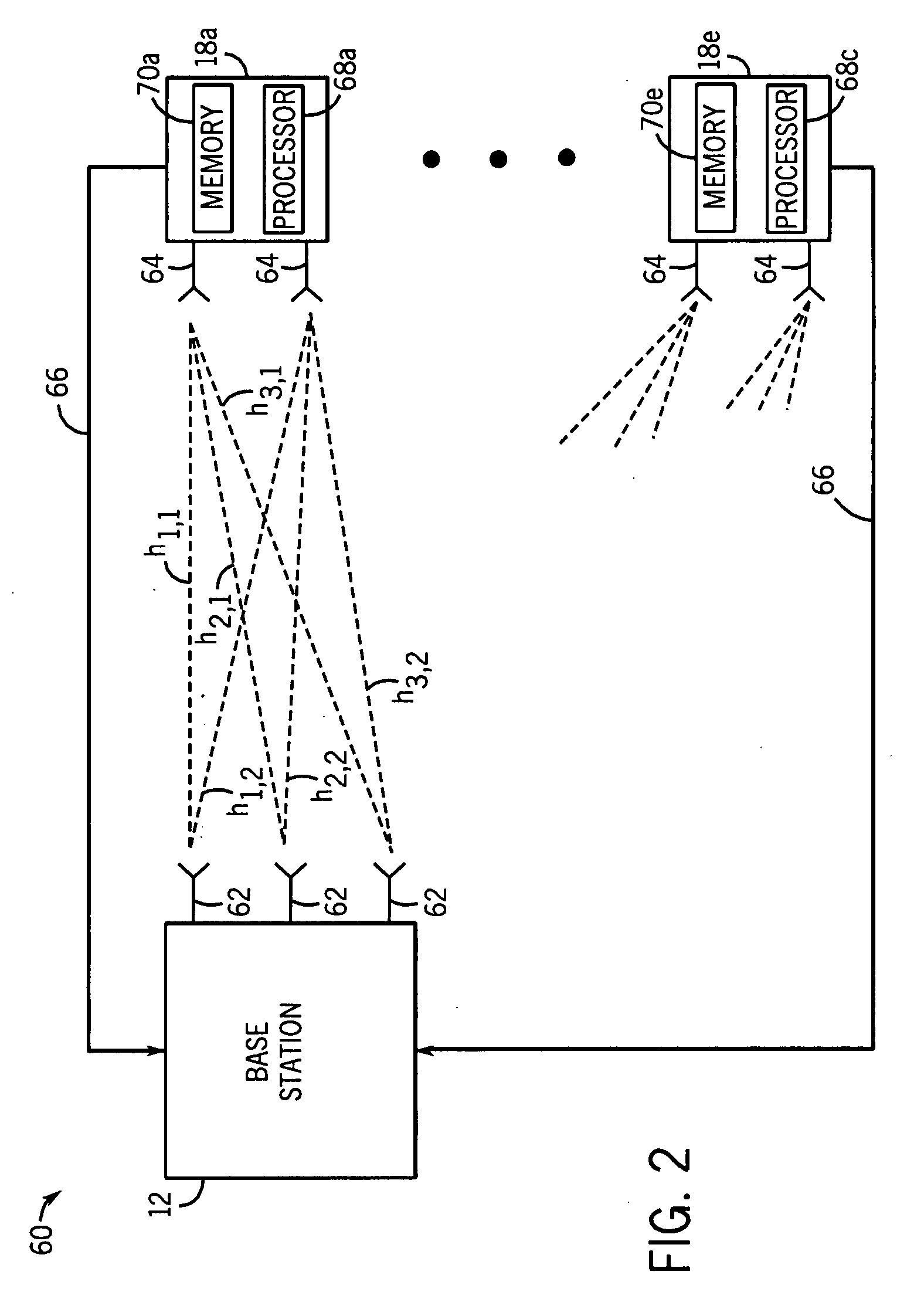
[0014]In accordance with an exemplary embodiment of the present invention, there is provided a method of operating a receiver with N antennas in a MIMO system. The method includes measuring N vectors, each vector defining channel transfer coefficients between M antennas of a transmitter and a corresponding antenna of the receiver. A vector in a linear space generated by the N measured vectors is selected and quantized values of less than M components of the selected vector are fed back to the transmitter.
[0015]In accordance with an alternative embodiment, there is provided a communication system. The communication system includes a receiver with N antennas and a multiple-input multiple-output (MIMO) transmitter with M antennas. The transmitter is configured to communicate data from the M antennas to the N antennas of the receiver. The receiver is configured to measure N vectors in response to the transmitter transmitting pilot signals, each vector defining channel transfer coefficients between the M antennas of the transmitter and a corresponding antenna of the receiver. Additionally, the receiver is configured to select a vector in a linear space generated by the measured vectors and to feed back quantized values of less than M components of the selected vector to the transmitter.

Problems solved by technology

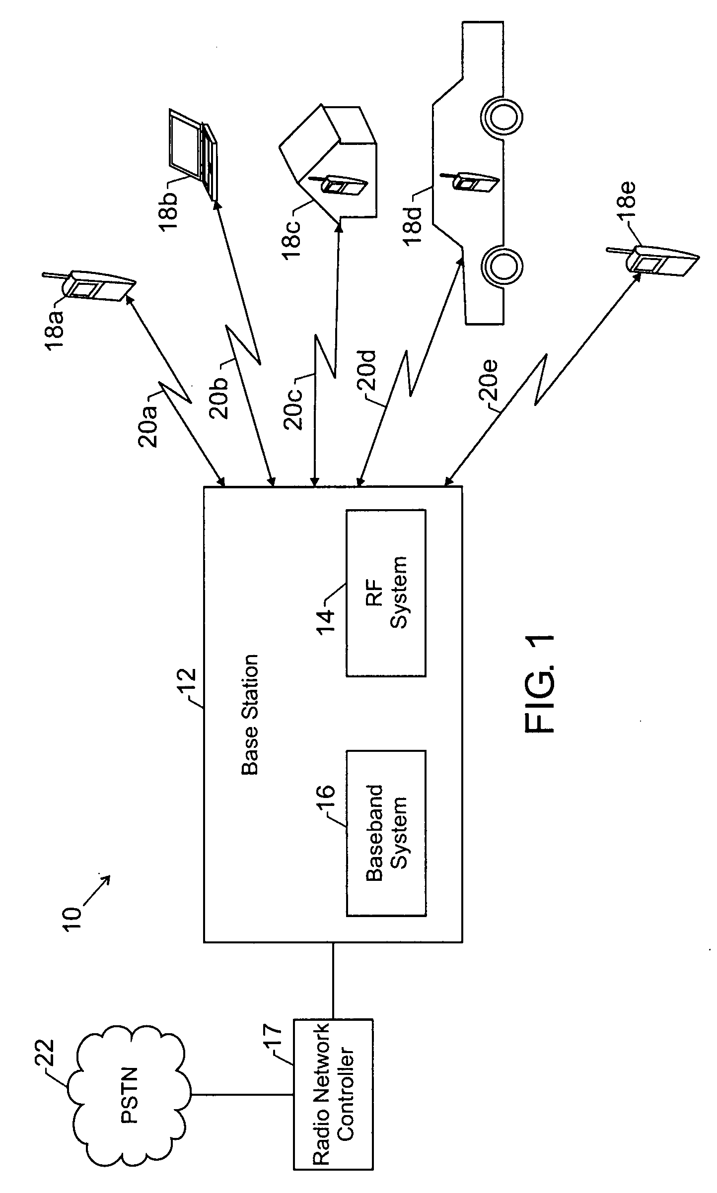
The convenience and usefulness of wireless communications cannot be understated.
Unfortunately, the brute force implementation of step 2 of the above algorithm has a high level of complexity and is computationally burdensome.
There are no fast algorithms for searching among the code vectors of the codebook C to find the code vector with the smallest angle between the vector and the multidimensional space Q. As such, using contemporary techniques, the measurements may require extensive hardware and / or software in the receiver and / or extensive processing time in the receiver.
However, only a limited amount of time and resources are available for any feedback transmission from a receiver.

Method used


Image

  • Providing feedback in a MIMO system
  • Providing feedback in a MIMO system
  • Providing feedback in a MIMO system

Examples


Embodiment Construction

[0020]One or more specific embodiments of the present invention will be described below. In an effort to provide a concise description of these embodiments, not all features of an actual implementation are described in the specification. It should be appreciated that in the development of any such actual implementation, as in any engineering or design project, numerous implementation-specific decisions should be made to achieve the developers' specific goals, such as compliance with system-related and business-related constraints, which may vary from one implementation to another. Moreover, it should be appreciated that such a development effort might be complex and time consuming, but would nevertheless be a routine undertaking of design, fabrication, and manufacture for those of ordinary skill having the benefit of this disclosure.

[0021]In accordance with present techniques, there is provided a system and method for efficiently providing channel vector measurements as feedback to ...


PUM


Abstract

There is provided a system and method of operating a multiple-input multiple-output (MIMO) receiver with N antennas in a wireless communication system. The method includes measuring N vectors, each vector defining channel transfer coefficients between M antennas of a transmitter and a corresponding antenna of the receiver. Additionally, a vector in a linear space generated by the N measured vectors is selected and quantized values of less than M components of the selected vector are fed back to the transmitter.

Description

BACKGROUND OF THE INVENTION[0001]1. Field of the Invention[0002]The present invention is related to communication systems. More particularly, the present invention is related to wireless communication systems having multiple transmitter and receiver antennas.[0003]2. Discussion of the Related Art[0004]This section is intended to introduce the reader to various aspects of art that may be related to various aspects of the present invention, which are described and claimed below. This discussion is believed to be helpful in providing the reader with background information to facilitate a better understanding of the various aspects of the present invention. Accordingly, it should be understood that these statements are to be read in this light, and not as admissions of prior art.[0005]Over the past several decades, the wireless communications industry has grown at an incredible rate. The convenience and usefulness of wireless communications cannot be understated. Indeed, the devices whi...

Claims


Application Information

Patent Timeline
Patent Type & Authority Applications(United States)
IPC IPC(8): H04B7/02H04L1/02
CPCH04B7/0417H04B7/0663H04B7/0639H04B7/0626H04B7/0421H04B7/0482
Inventor ASHIKHMIN, ALEXEI
Owner ALCATEL LUCENT SAS
Learn More